Air Treatment Device

a technology for air treatment and air, which is applied in the direction of auxillary pretreatment, separation process, filtration separation, etc., can solve the problem of inability to operate, and achieve the effect of convenient and user-friendly loading and unloading, convenient loading and unloading, and sufficient mechanical grip

Inactive Publication Date: 2015-04-30
RECKITT & COLMAN OVERSEAS LTD
View PDF4 Cites 0 Cited by
  • Summary
  • Abstract
  • Description
  • Claims
  • Application Information

AI Technical Summary

Benefits of technology

[0010]Keeping the airflow separate is considered to be particularly advantageous and efficient for several reasons, in particular because accelerated airflow generated by the fan will not come into contact with the heater(s) thus will not require the heater(s) to use more energy in imparting a sufficient amount of heat toward the refill of air treatment agent. Additionally it will permit a user to operate the two functions of the device independently as necessary; this ability would not be possible if separated air passageways and airflows were not available.
[0015]The movement of the air filter held in the device by the retaining means when the door is moved by a user to the door's second position is considered to be particularly advantageous as the air filter will be presented for visual inspection to the user regardless of whether the user intended to inspect the filter or not. Although the user may not be able to perceive the improved air quality related to the reduction of airborne pollutants when using the device, such a presentation of the air filter for visual inspection to the user will permit the user to appreciate that they are improving the air quality by reducing the level of airborne pollutants in addition to any improvements in perceived air quality related to the emanation of air treatment agent into the surrounding environment.
[0016]Preferably the device is provided with a single air inlet and single air outlet, and preferably both of said air inlet and air outlet being covered by vents to object the access of large objects and improve the safe operation of the device when in use. Most preferably the device is provided with two air inlets and one air outlet.
[0026]Preferably the device is provided with guide means for the refill of air treatment agent to permit more convenient and user-friendly loading and unloading thereof. The device is preferably provided with a sufficiently sized recess or the like to permit ease of lateral access to the refill or refills when secured in the device to permit a user to sufficient mechanical grip on the refill(s) for convenient loading and unloading of said refill(s).

Problems solved by technology

Additionally it will permit a user to operate the two functions of the device independently as necessary; this ability would not be possible if separated air passageways and airflows were not available.

Method used


Image

  • Air Treatment Device
  • Air Treatment Device
  • Air Treatment Device

Examples


Embodiment Construction

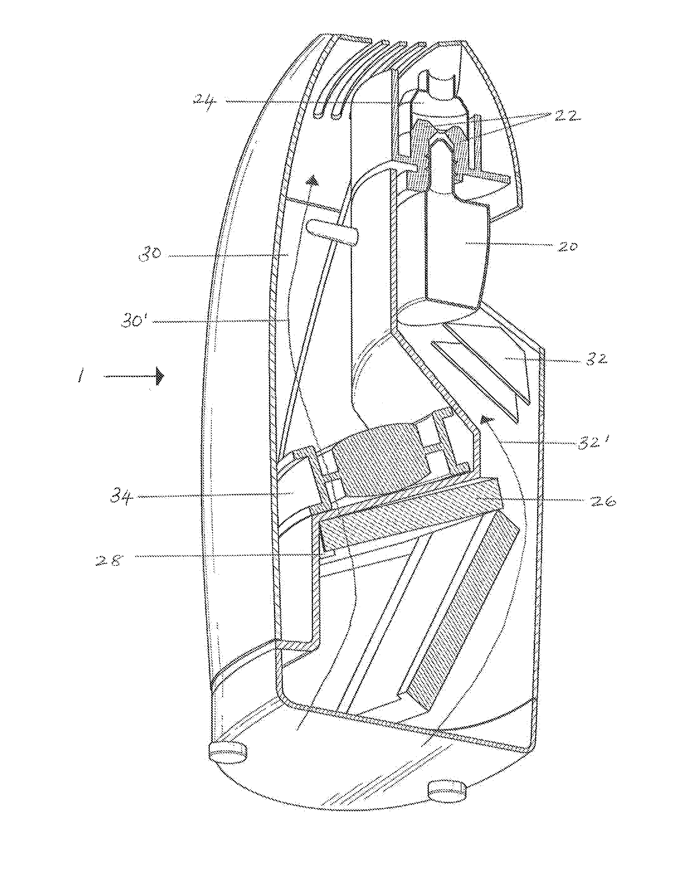
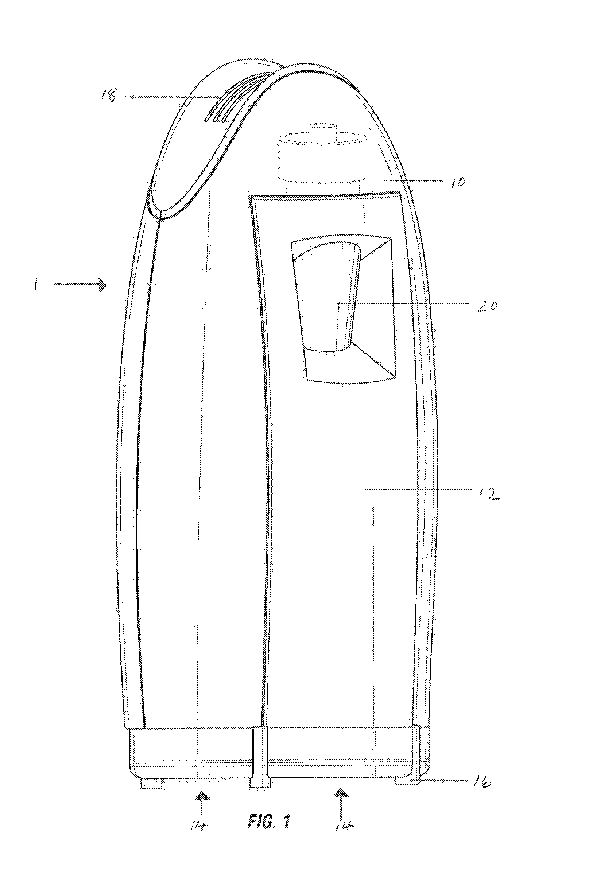
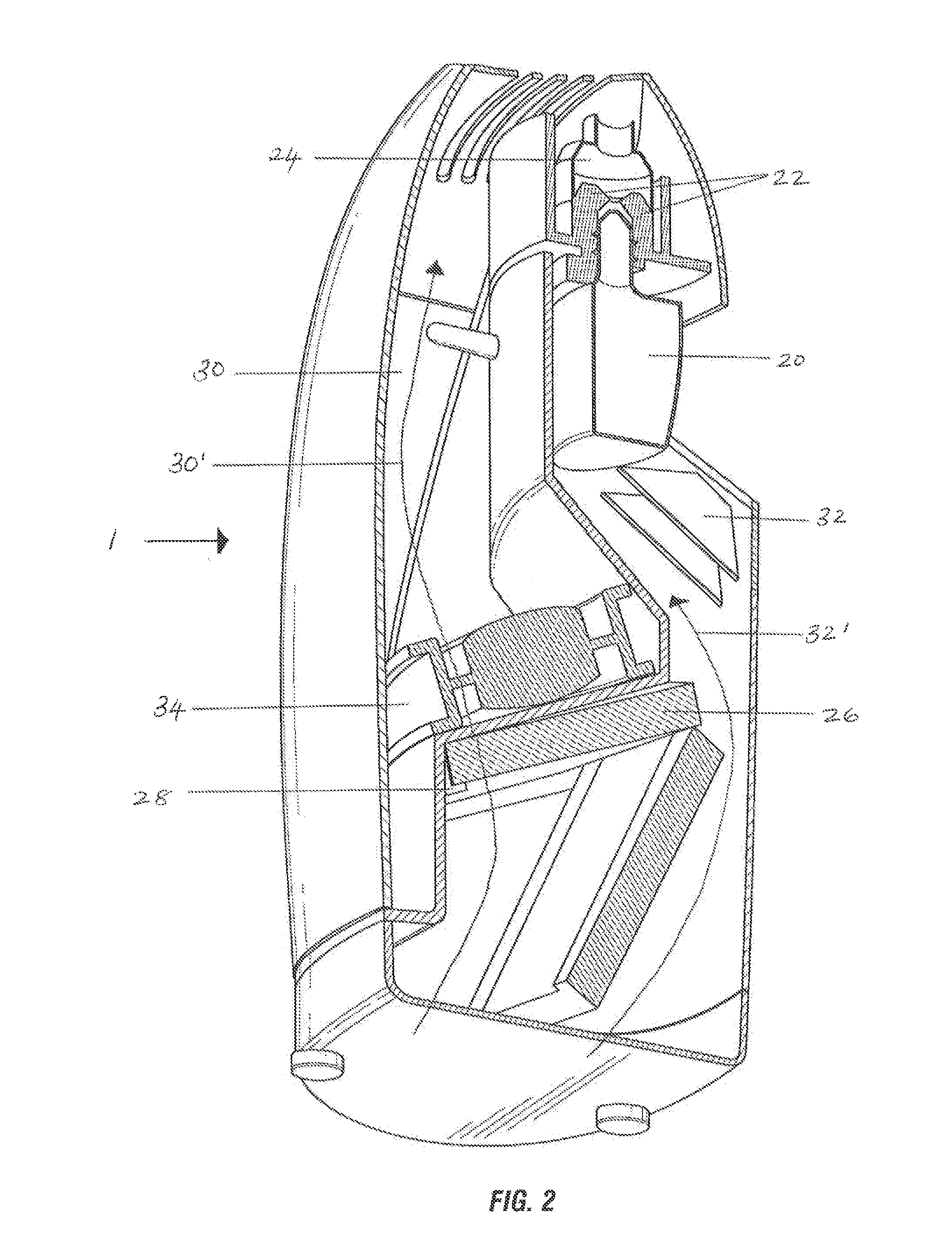
[0038]As can been seen with reference to both FIGS. 1 & 2, the device 1 of the present invention has a generally elongate housing 10 with an elongate door 12 therein. At the base of the device is an air inlet 14 which is spaced above a surface on which the device is to be placed during use thereof by a plurality of feet 16 protruding from the base. At the upper portion of the housing 10 is an air outlet 18.

[0039]The device 1 is illustrated with a bottle of air treatment agent 20 engaged therein. The bottle 20 is located within the device in registration with a window in the door 12 to conveniently permit a user of the device to determine the level of agent remaining in the bottle 20.

[0040]As can be seen with specific reference to FIG. 2, the bottle 20 is secured in the device via releasable engagement with securing means 22 which grip the neck of the bottle 20, this enables a wick (not shown) to protrude out of the top of the bottle 20 and into an aperture within a heater 24 located...


PUM

PropertyMeasurementUnit
perimeteraaaaaaaaaa
energyaaaaaaaaaa
angleaaaaaaaaaa

Abstract

An air treatment device is described comprising: a housing having at least one air inlet and at least one air outlet with at least two discrete air passageways therebetween; wherein in a first of said passageways there is located a fan and at least one air filter retaining means arranged to releasably retain, in use, an air filter within one passageway; and wherein in a second of said passageways there is located at least one refill securing means arranged to releasably securing a refill of air treatment agent and emanation means in the form of one or more heaters; and wherein, in use, airflow through said at least two passageways is separate.

Description

FIELD OF THE INVENTION[0001]The present invention relates to a device for treating the air and particularly but not exclusively, for treating the air to remove contaminants and / or malodour therefrom as well as introduce an air treatment agent thereto.BACKGROUND[0002]Increasing the amount of indoor air pollution is being linked to the affects it may have on a person's health. Certain studies suggest that indoor air can be significantly more polluted than outdoor air which may be of particular concern to people spending a majority of their time indoors.[0003]Consequently it has become increasingly desirable to treat the air in localized environments to not only improve its perceived quality but also its actual quality by attempting to remove some of the more common indoor air pollutants, including dust, smoke, pollen, bacteria, soot, mould spores, animal dander, and other microscopic irritants, as well as attempting to remove malodour and thereby create a clean, healthy, fresh, and pl...

Claims


Application Information

Patent Timeline
Patent Type & Authority Applications(United States)
IPC IPC(8): B01D46/00B01D46/42
CPCB01D46/0038B01D46/0002B01D46/4263A61L9/032A61L9/037A61L2209/133A61L2209/14A61L2209/15A61L9/122B01D2273/14
Inventor CONYERS, ANDREAGARCIA, REUBENGOMEZ, JUAN ANTONIOHINDLE, BENJAMIN DAVIDROPIC, MELANIEWALSH, STEVE
Owner RECKITT & COLMAN OVERSEAS LTD
Why Eureka
Try Eureka