Control device for mobile body

a control device and mobile body technology, applied in the field of mobile body control devices, can solve the problems of difficult implementation of smooth transition operations and difficult application of gait generation operation models in patent literature, and achieve the effect of accurate expression of transition operations and smooth operation

Active Publication Date: 2017-06-20
HONDA MOTOR CO LTD
View PDF10 Cites 2 Cited by
  • Summary
  • Abstract
  • Description
  • Claims
  • Application Information

AI Technical Summary

Benefits of technology

[0011]It is therefore an object of the present invention to provide a control device for a mobile body which enables smooth transition operations between a first mode and a second mode.
[0017]In the desired transition operation between the first mode and the second mode which differ in the height of the center of gravity from each other, the transition operation involves the change of the height of the center of gravity. As the dynamic model is expressed using the displacement-dependent manipulated variable component which changes on a time-series basis in accordance with the instantaneous values of the desired displacement in the up-and-down direction, the desired transition operation is expressed more appropriately by the dynamic model. As a result, the desired motion in the first mode and the desired transition operation between the first mode and the second mode may be implemented more smoothly.
[0019]According to the control device for the mobile body with the above configuration, the rotational motion component is dependent on the instantaneous value of the desired displacement in the up-and-down direction of the base body, so the rotational motion component may more accurately express the transition operation involving the shift of the center of gravity. As a result, the transition operation between the first mode and the second mode may be performed more smoothly.
[0025]According to the control device for the mobile body with the above configuration, in the transition operation between the first mode and the second mode which differ in the height of the center of gravity from each other, while the height of the center of gravity can be changed by rotation of the second base body, large fluctuation in posture of the first moving mechanism, which functions as the moving mechanism in both of the first and second modes, with respect to the first base body during the transition operation may be avoided or alleviated. Further, as the mobile body in the dynamic model used for generating the desired motion in the first mode is expressed using the first rotational motion component and the second rotational motion component, the transition operation of the mobile robot involving the rotational motion of the first base body and the rotational motion of the second base body is expressed using that dynamic model. As a result, the desired transition operation is generated using the same dynamic model as the one used for generating the desired motion in the first mode. It thus becomes unnecessary to switch the dynamic model when performing the transition operation, ensuring that a series of operations from generation of a desired transition operation to execution of the transition operation may be implemented smoothly.
[0028]According to the control device for the mobile body with the above configuration, the second rotational motion component is dependent on the instantaneous value of the desired displacement in the up-and-down direction of the base body, so the second rotational motion component may more accurately express the transition operation involving the shift of the center of gravity. As a result, the transition operation between the first mode and the second mode may be performed more smoothly.
[0031]According to the control device for the mobile body with the above configuration, the first rotational motion component is dependent on the instantaneous value of the desired displacement in the up-and-down direction of the base body, so the first rotational motion component may more accurately express the transition operation involving the shift of the center of gravity. As a result, the transition operation between the first mode and the second mode may be performed more smoothly.

Problems solved by technology

The technique of Patent Literature 1, however, is based on the biped movement, so it would be difficult to apply the operation model for the gait generation in Patent Literature 1, as it is, to generation of the transition operations between the biped state and the quadruped state.
As such, implementation of smooth transition operations was difficult.

Method used


Image

  • Control device for mobile body
  • Control device for mobile body
  • Control device for mobile body

Examples


first embodiment

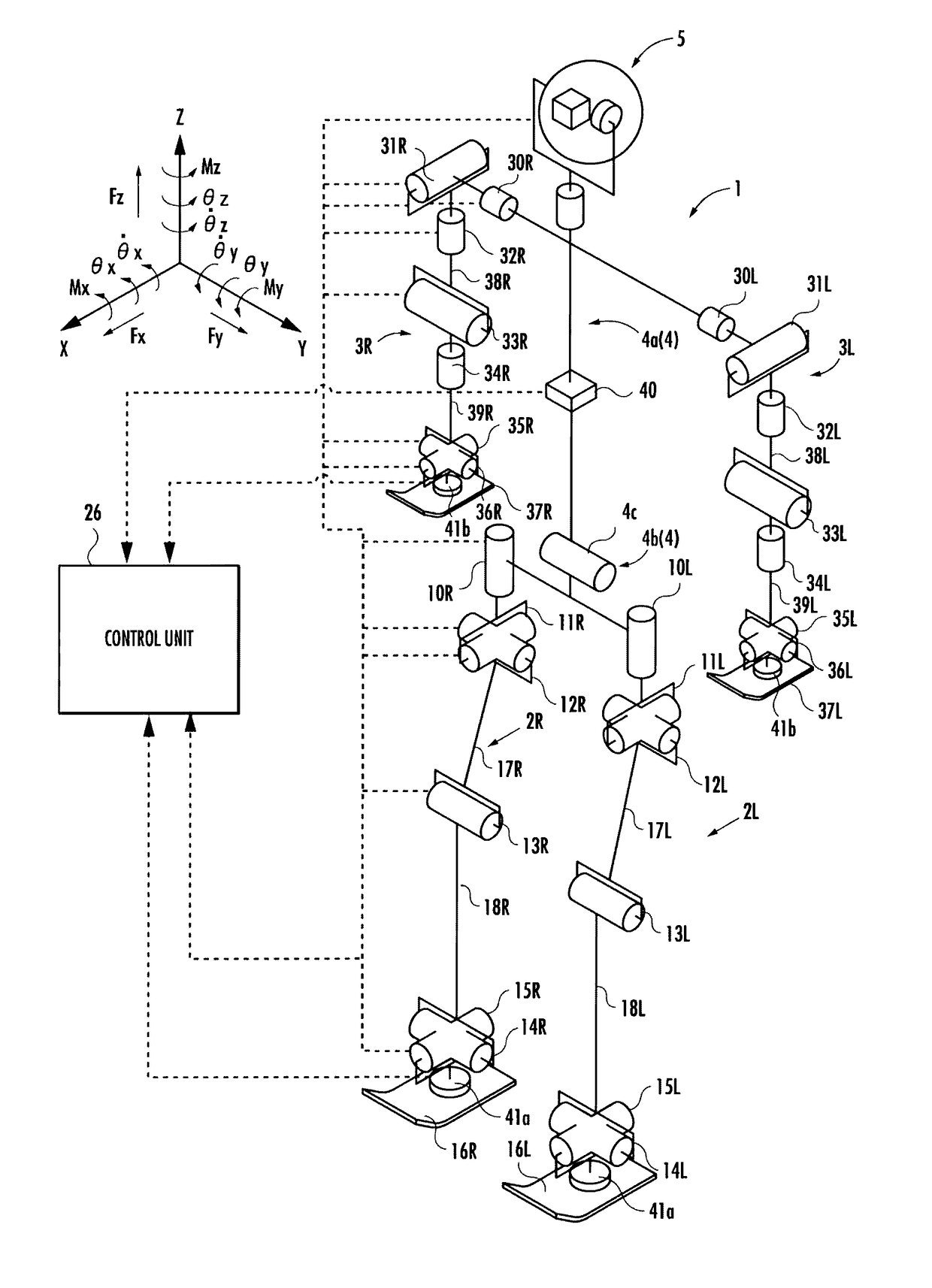
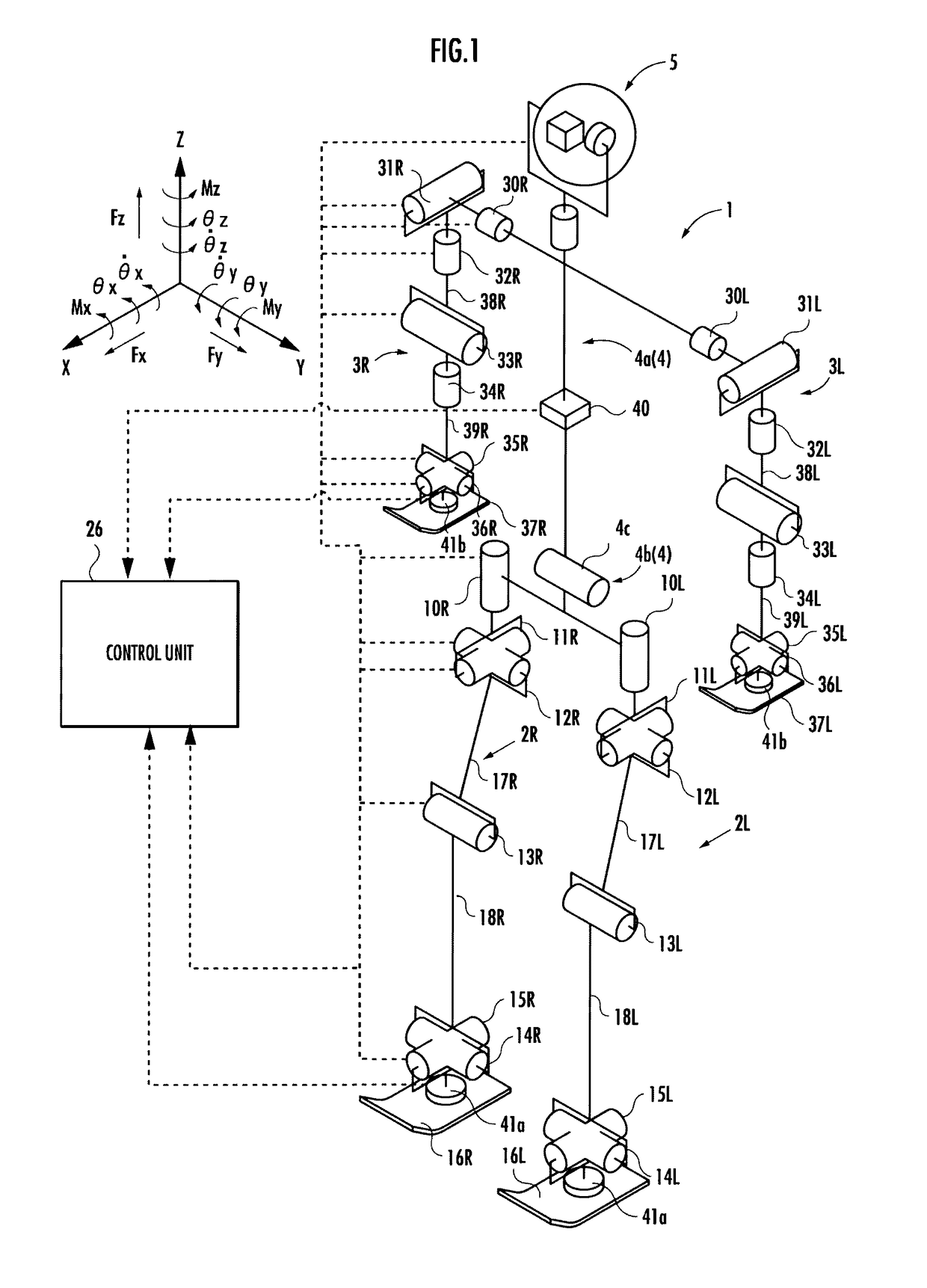
[0115]As shown in FIG. 1, a biped / quadruped mobile robot 1 (hereinafter, simply referred to as “robot 1”) of a first embodiment includes a body 4 (corresponding to the “base body” of the present invention) as a base body and, as a moving mechanism that moves the body 4 on the floor surface, a pair of right and left lower limbs (legs) 2R, 2L (corresponding to the “first moving mechanism” of the present invention) interposed between the body 4 and the floor, and a pair of right and left upper limbs (arms) 3R, 3L (corresponding to the “second moving mechanism” of the present invention) attached to the respective sides of the upper portion of the body 4.

[0116]The robot 1 is configured to be able to make transitions between a biped state (first mode), in which the body 4 is supported above the floor surface by the lower limbs 2R, 2L landed on the floor, and a quadruped state (second mode), in which the body 4 is supported above the floor surface by the lower limbs 2R, 2L and the upper li...

second embodiment

[0226]the present invention differs from the first embodiment in that the following expressions 108e and 108f are used in place of the expressions 108c and 108d in the first embodiment. It is noted that h1 represents an average value of the center of gravity of the robot 1 at the time of biped walking.

[0227]ω⁡(t)=g+ⅆ2ⅆt2⁢Zb⁡(t)h⁢⁢1Expression⁢⁢108⁢eφi⁡(t)=Iimb*h⁢⁢1⁢⁢i=1,2Expression⁢⁢108⁢f

third embodiment

[0228]the present invention differs from the first embodiment in that the following expression 106b is used in place of the expression 106a in the first embodiment.

[0229]B⁡(k)=[b1φ1⁡(k)⁢b1b2φ1⁡(k)⁢b2]Expression⁢⁢106⁢b

[0230]A comparative embodiment differs from the first embodiment in that the above expressions 106b, 108e, and 108f are used in place of the expressions 106a, 108c, and 108d in the first embodiment.

[0231]Referring to FIG. 9, an operation of the dynamic calculation section of the gait generation system 100 (shown in FIG. 3) will be described. A horizontal position calculator 200 in the dynamic calculation section calculates a body mass point horizontal position Xb from a desired ZMP in accordance with the expression 100.

[0232]Further, as shown inFIG. 9, the dynamic calculation section includes a body position determiner 202. The body position determiner 202 determines the horizontal position of the body from the body mass point horizontal position Xb.

[0233]Continuous pos...


PUM


Abstract

A control device for a mobile body enabling a smooth transition operation between a first mode and a second mode is provided. A change amount of a center of gravity component at a prescribed time is expressed by using an inertial force-dependent manipulated variable component, which changes in accordance with an instantaneous value (d2Zb / dt2(t1) to d2Zb / dt2(t13)) of desired inertial force at the prescribed time (t1 to t13) in the time series of the desired inertial force (d2Zb / dt2(t)) defined by an up-and-down direction motion parameter, and a displacement-dependent manipulated variable component, which changes in accordance with an instantaneous value (Zb(t1) to Zb(t13)) of desired displacement at the prescribed time (t1 to t13) in the time series of the desired displacement (Zb(t)) defined by the up-and-down direction motion parameter.

Description

BACKGROUND OF THE INVENTION[0001]Field of the Invention[0002]The present invention relates to a control device for a mobile body.[0003]Description of the Related Art[0004]As a mobile body having a base body and a moving mechanism that moves the base body on a floor surface, a biped mobile robot, for example, is generally known. In the biped mobile robot, legs correspond to the moving mechanism and a body corresponds to the base body.[0005]Regarding the biped mobile robot, for example, a technique of setting a desired motion trajectory on the basis of a ZMP stability standard has been proposed (see, for example, Patent Literature 1).[0006][Patent Literature 1] Japanese Patent No. 5232120SUMMARY OF THE INVENTION[0007]In recent years, for further improvement in motion capability, a legged mobile robot is desired to make transition operations between an ordinary biped state using two legs and a quadruped state for moving in a narrow space or when it stumbles.[0008]To enable a smooth tra...

Claims


Application Information

Patent Timeline
Patent Type & Authority Patents(United States)
IPC IPC(8): G06F19/00B25J9/16B62D57/032
CPCB25J9/1605B62D57/032Y10S901/01
Inventor KAMIOKA, TAKUMIKANEKO, HIROYUKITANAKA, CHIAKI
Owner HONDA MOTOR CO LTD
Why Eureka
Try Eureka