
Detachable lighting source device having a light guiding wire set equipped with a detachable lighting source

a technology of lighting source and light guiding wire, which is applied in the direction of fibre light guides, lighting and heating apparatus, instruments, etc., can solve the problems of power module weight, power module charge or battery change, and difficulty in managing battery level, so as to reduce the weight and facilitate the power supply

Inactive Publication Date: 2017-06-20
WANG PO FENG
View PDF5 Cites 3 Cited by
  • Summary
  • Abstract
  • Description
  • Claims
  • Application Information

AI Technical Summary

Benefits of technology

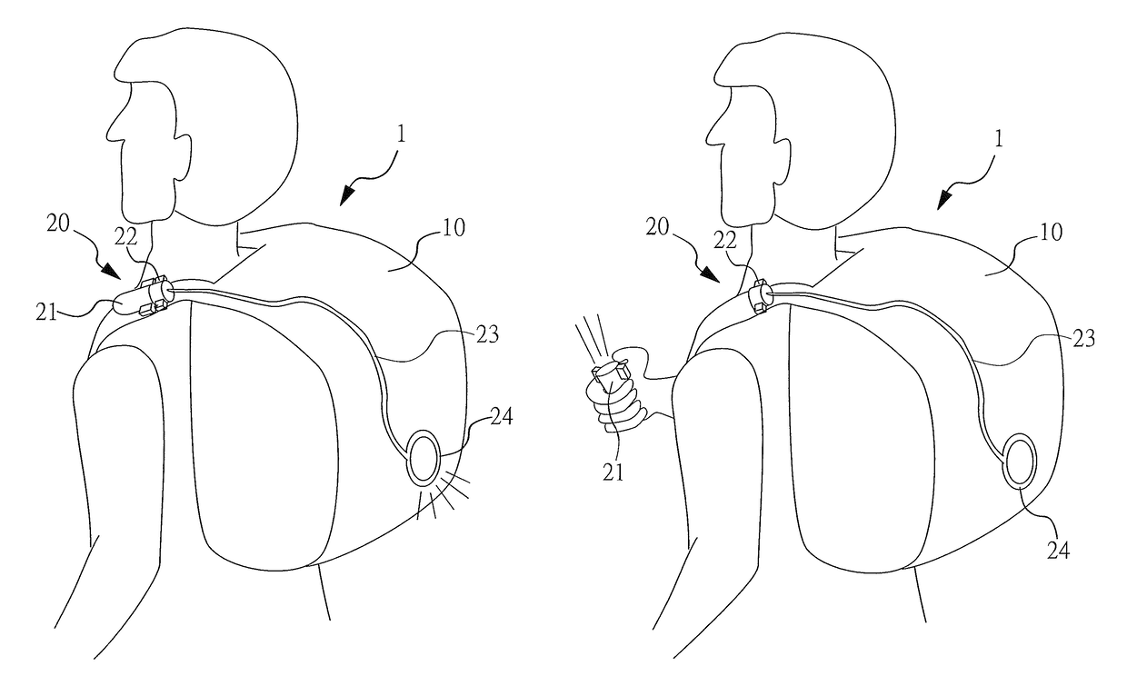
[0007]It is an object of the present invention to provide a device having a light guiding wire set equipped with a detachable lighting source. The light guiding wire set equipped with a detachable lighting source can be charged by an external power module to achieve power supply flexibility, to avoid the task of changing batteries, and to reduce the weight. Furthermore, when the illuminating apparatus is detached from the light guiding wire set, the illuminating apparatus can be independently illuminated.
[0011]The illuminating apparatus is a lighting device, and the detachable connecting device is situated between the illuminating apparatus and the at least one light guiding wire. The detachable connecting device facilitates quick connection and detachment of the illuminating apparatus. Therefore, the illuminating apparatus can be quickly connected with the detachable connecting device and the light generated by the illuminating apparatus can be transmitted via the light guiding wire to achieve the effects of displaying, guiding, alerting, illuminating or decorating. The illuminating apparatus is detachably connected with the detachable connecting device and can be illuminated independently.

Problems solved by technology

The drawbacks of the above-mentioned art are that the power module has a certain weight, and that the power module has to be charged or that batteries have to be changed when the battery level is low.
Furthermore, individual devices are equipped with specific power modules; i.e., the devices cannot be charged from mobile devices.
As a result, it is difficult to manage the battery level, and the method for using the lighting device is complicated.

Method used


Image

  • Detachable lighting source device having a light guiding wire set equipped with a detachable lighting source
  • Detachable lighting source device having a light guiding wire set equipped with a detachable lighting source
  • Detachable lighting source device having a light guiding wire set equipped with a detachable lighting source

Examples


Embodiment Construction

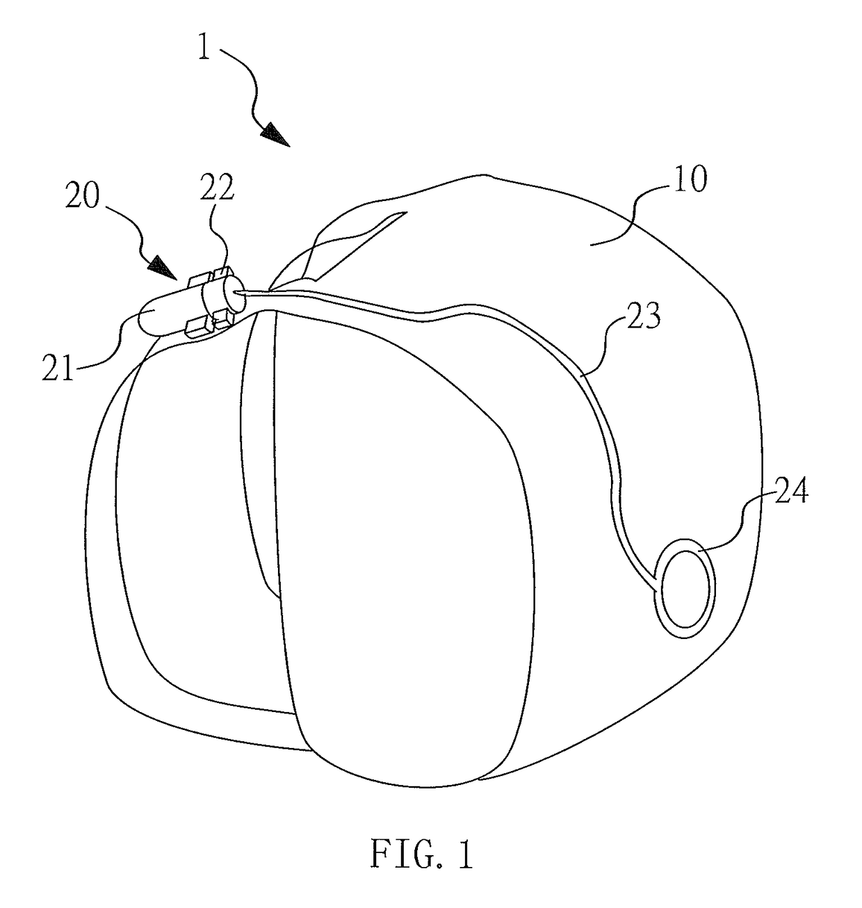
[0019]The technical content of the invention will become more apparent from the following detailed descriptions of several preferred embodiments. Please refer to FIG. 1, which depicts one embodiment of the device having a light guiding wire set equipped with a detachable lighting source.

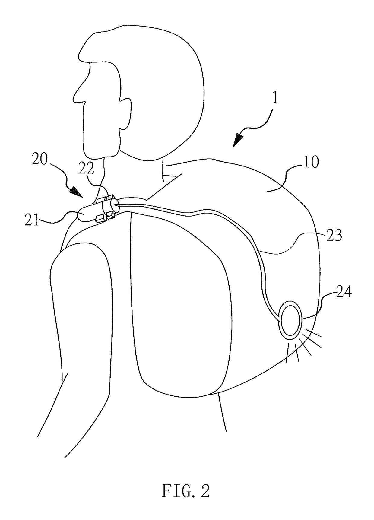
[0020]According to one embodiment, the device having a light guiding wire set equipped with a detachable lighting source 1 comprises a main body 10 and a light guiding wire set 20 with a detachable lighting source. The light guiding wire set 20 with a detachable lighting source is connected with the main body 10. In the present embodiment, the main body 10 is a backpack, but the present invention is not limited to this embodiment. The light guiding wire set 20 with a detachable lighting source comprises an illuminating apparatus 21, a detachable connecting device 22, and at least one light guiding wire 23. The illuminating apparatus 21 can be connected with or detached from the detachable connecting ...


PUM


Abstract

A device includes a main body and a light guiding wire set. The light guiding wire set has an illuminating apparatus, a detachable connecting device and at least one light guiding wire. When the illuminating apparatus connects with the detachable connecting device, the light provided by the illuminating apparatus is transmitted via the light guiding wire to achieve the effects of displaying, guiding, alerting, illuminating or decorating.

Description

BACKGROUND OF THE INVENTION[0001]1. Field of the Invention[0002]The present invention relates to a device having a light guiding wire set equipped with a detachable lighting source and, more particularly, to a device equipped with a detachable illuminating apparatus.[0003]2. Description of the Related Art[0004]The lighting sources of backpacks for providing lighting features are powered by batteries or power modules. For example, the lighting devices of the “Illuminator for backpack” disclosed in TW M290689 and “Marquee bags” disclosed in TW M412663 are both powered by batteries.[0005]The drawbacks of the above-mentioned art are that the power module has a certain weight, and that the power module has to be charged or that batteries have to be changed when the battery level is low. Furthermore, individual devices are equipped with specific power modules; i.e., the devices cannot be charged from mobile devices. As a result, it is difficult to manage the battery level, and the method ...

Claims


Application Information

Patent Timeline
Patent Type & Authority Patents(United States)
IPC IPC(8): F21L4/00F21V8/00F21L4/04A45F3/00A45F3/04A45C15/06
CPCG02B6/001F21L4/00F21L4/045G02B6/0006A45C15/06A45F3/04A45F2003/001A45F2003/003
Inventor WANG, PO-FENG
Owner WANG PO FENG
Learn More