
Continuous annealing furnace and continuous annealing method for steel strips

a technology of continuous annealing and furnace, which is applied in the direction of furnaces, heat treatment equipment, lighting and heating equipment, etc., can solve the problems of long time to reduce the concentration of water and oxygen in the furnace atmosphere to the prescribed levels, reduce productivity, and deteriorate the appearance or chemical conversion property such as phosphatability, so as to prevent a decrease in productivity and shorten the period of time , the effect of stable production of steel strips

Active Publication Date: 2017-07-11
JFE STEEL CORP
View PDF23 Cites 1 Cited by
  • Summary
  • Abstract
  • Description
  • Claims
  • Application Information

AI Technical Summary

Benefits of technology

[0016]The present invention aims to provide a continuous annealing furnace for steel strips which can lower quickly the dew point of the furnace atmosphere to a level suited for steady operation,
[0019]Further, the present invention includes providing a continuous annealing furnace for steel strips which can stably create a low-dew point atmosphere having little problems in terms of the occurrence of pick-up defects and damages to furnace walls, which prevents the formation of oxides of easily oxidizable elements such as silicon and manganese in the steel that have become concentrated at the surface of steel strips during annealing, and which is hence suited for the annealing of steel strips containing easily oxidizable elements such as silicon.
[0023]The present inventors have carried out studies including the measurement of dew point distribution in a large multi-pass vertical furnace and rheological analysis based on the distribution. As a result, the present inventors have found the following. Because steam (H2O) has a lower specific gravity than N2 gas which occupies the major proportion of the atmosphere, the dew point in a multi-pass vertical annealing furnace tends to be higher at an upper portion in the furnace. A local increase in the dew point at an upper portion of the furnace can be prevented and the dew point of the furnace atmosphere can be decreased in a short time to a prescribed level suited for steady operation by suctioning and sending the gas in the furnace through an upper part of the furnace into a refiner equipped with an oxygen removal device and a dehumidifier to lower the dew point by the removal of oxygen and water, and thereafter returning the gas having the lowered dew point into a specific section in the furnace. Further, in the above manner, the dew point of the furnace atmosphere can be stably maintained at a low level where little problems occur in terms of pick-up defects and damages to furnace walls and also at which the formation is prevented of oxides of easily oxidizable elements such as silicon and manganese in the steel that have become concentrated at the surface of steel strips during annealing.
[0036]Prior to the steady operation of continuous heat treatment of a steel strip or when the water concentration and / or the oxygen concentration in the furnace atmosphere has increased during the steady operation, the continuous annealing furnace for steel strips according to the present invention can shorten a period of time that the water concentration and / or the oxygen concentration in the furnace atmosphere is reduced to such a level where the dew point of the furnace atmosphere is lowered to −30° C. or below, permitting stable production of steel strips. Thus, the inventive furnace preferably prevents a decrease in productivity.
[0037]Further, the inventive furnace for continuous annealing of steel strips allows the furnace atmosphere to stably maintain a low dew point of −40° C. or below where little problems occur in terms of pick-up defects and damages to furnace walls and also at which the formation is prevented of oxides of easily oxidizable elements such as silicon and manganese in the steel that have become concentrated at the surface of steel strips during annealing. Further, the inventive furnace for continuous annealing of steel strips allows for easy manufacturing of steels such as Ti-containing IF steel which do not favor operation in a high-dew point atmosphere.

Problems solved by technology

However, such conventional methods require a long time to decrease the concentrations of water and oxygen in the furnace atmosphere to prescribed levels suited for steady operation.
Thus, the discontinuation of operation during such a time drastically lowers productivity.
However, high-strength cold rolled steel strips containing easily oxidizable elements such as silicon and manganese have a problem in that these easily oxidizable elements are concentrated at the surface of the steel strips during annealing to form oxides such as of silicon and manganese, deteriorating appearance or chemical conversion property such as phosphatability.
In the case of hot dip galvanized steel strips, the presence of easily oxidizable elements such as silicon and manganese in the steel strips causes a problem that these easily oxidizable elements are concentrated at the surface of the steel strips during annealing to form oxides such as of silicon and manganese, and such oxides impair coating properties to cause the occurrence of bare-spot defects or to decrease the alloying speed during an alloying treatment after the coating process.
In particular, silicon is highly detrimental to coating properties and alloying treatments because a SiO2 film formed on the surface of a steel strip markedly lowers the wettability of the steel strip with respect to a hot dip coating metal and also because a SiO2 film serves as a barrier during an alloying treatment to inhibit the interdiffusion between the base iron and the coating metal.
However, the technique is defective in that it does not allow for efficient production of some types of steel that do not favor being processed in a high-dew point atmosphere (for example, Ti-containing IF steel) because an annealing atmosphere once brought to a high dew point requires a very long time to become one having a low dew point.
In this technique, further, the furnace atmosphere is oxidative and, unless controlled appropriately, causes a problem of pick-up defects due to the attachment of oxides to rolls in the furnace as well as a problem of damage to the furnace walls.
However, because such elements as silicon and manganese are highly prone to oxidation, it has been considered that there will be great difficulties in stably maintaining the atmosphere with a low dew point of −40° C. or below at which excellent suppression is possible of the oxidation of elements such as silicon and manganese, in a large continuous annealing furnace such as one disposed in a CGL (continuous hot dip galvanization line)-CAL (continuous annealing line) system.
These techniques reside in relatively small, single-pass vertical furnaces and are not designed to be applied to multi-pass vertical furnaces such as CGL and CAL systems.
Thus, it is highly probable that these techniques will fail to decrease the dew point efficiently in a multi-pass vertical furnace.
Thus, difficulties are frequently encountered in decreasing the dew point in the entirety of the furnace.

Method used


Image

  • Continuous annealing furnace and continuous annealing method for steel strips
  • Continuous annealing furnace and continuous annealing method for steel strips
  • Continuous annealing furnace and continuous annealing method for steel strips

Examples


example 1

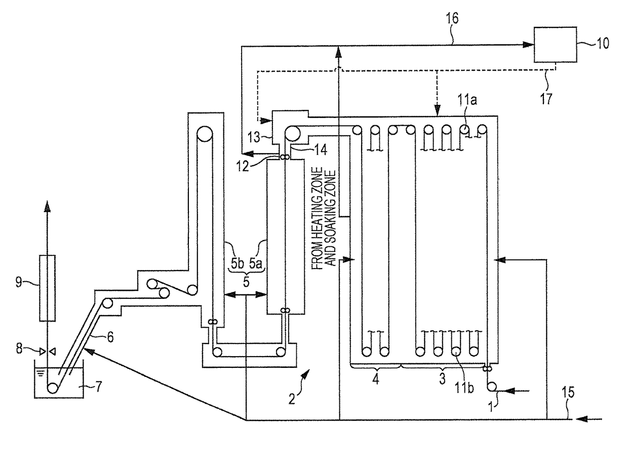
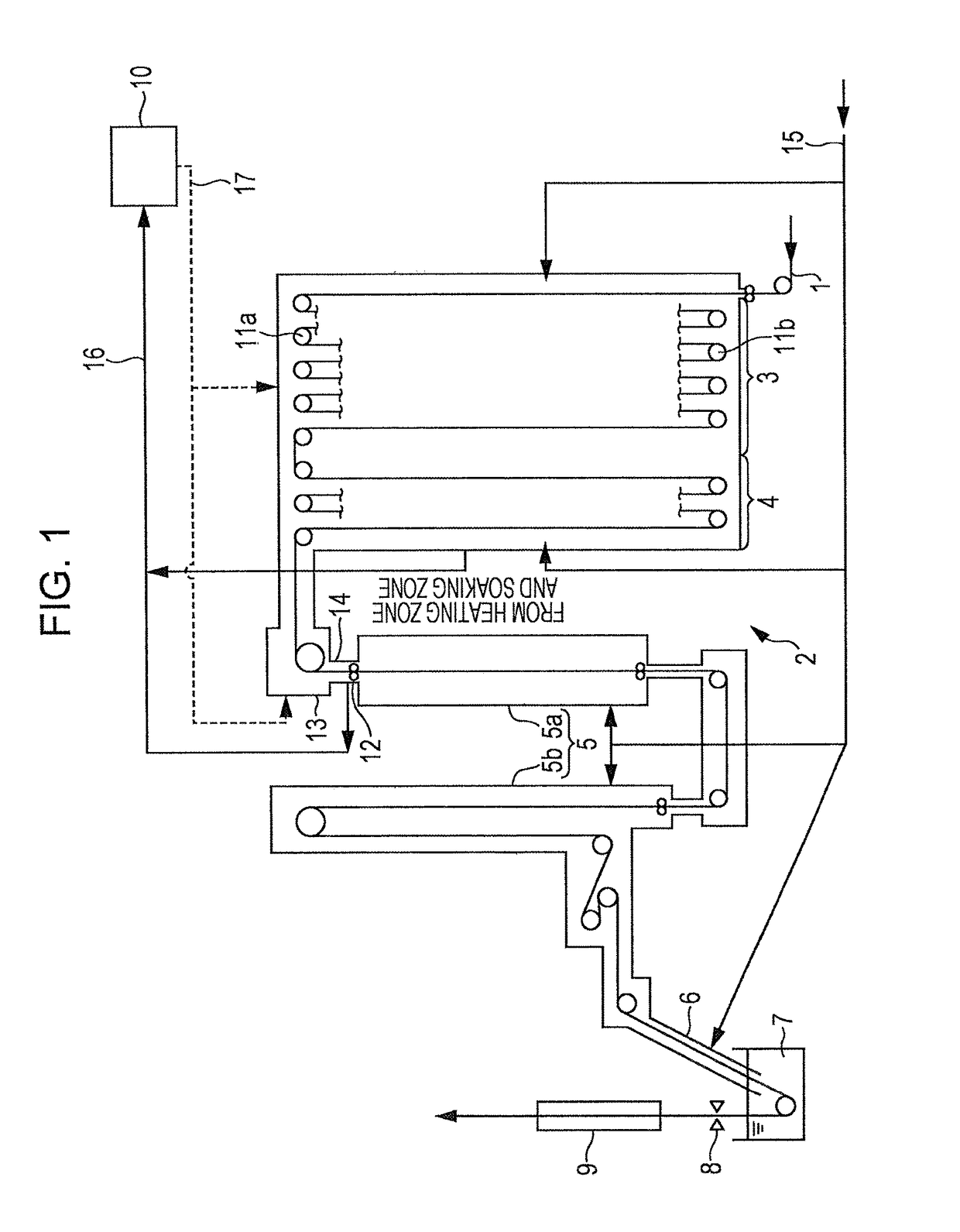
[0085]A dew point measurement test was carried out in an ART type (all radiant type) CGL illustrated in FIG. 1 (annealing furnace length: 400 m, furnace height in heating zone and soaking zone: 23 m, furnace width in heating zone: 12 m, furnace width in soaking zone: 4 m).

[0086]The furnace had openings through which the atmosphere gas from outside of the furnace is supplied at a total of six locations in the soaking zone, namely, at three locations arranged in the furnace length direction both at 1 m and 10 m above the hearth bottom on the drive side, and at a total of sixteen locations in the heating zone, namely, at eight locations arranged in the furnace length direction both at 1 m and 10 m above the hearth on the drive side. The dew point of the atmosphere gas to be supplied was −60° C.

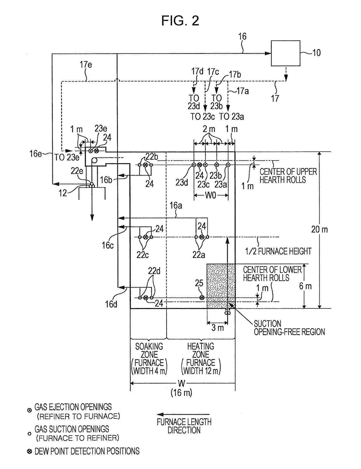
[0087]Furnace-to-refiner gas suction openings and refiner-to-furnace gas ejection openings were disposed as illustrated in FIG. 2. Specifically, the gas suction openings were disposed in a throat...

example 2

[0095]Trends of dew point decrease were studied with the ART type (all radiant type) CGL illustrated in FIG. 1 which was used in EXAMPLE 1.

[0096]The conditions in a conventional method (without the use of the refiner) were such that the atmosphere gas supplied into the furnace had a composition including 8 vol % H2 and the balance of N2 and inevitable impurities (dew point −60° C.), the rate of gas supply to the cooling zone and subsequent zones was 300 Nm3 / hr, the rate of gas supply to the soaking zone was 100 Nm3 / hr, the rate of gas supply to the heating zone was 450 Nm3 / hr, the steel strips had a sheet thickness of 0.8 to 1.2 mm and a sheet width of 950 to 1000 mm (the alloy components in the steel were the same as in Table 1), the annealing temperature was 800° C., and the line speed was 100 to 120 mpm.

[0097]The conditions in the inventive method were the same as the above conditions and further included the use of the refiner. The initial state of dew point was similar to the b...


PUM

PropertyMeasurementUnit
lengthaaaaaaaaaa
lengthaaaaaaaaaa
temperatureaaaaaaaaaa

Abstract

The invention provides a vertical annealing furnace including a heating zone and a soaking zone without any partition wall therebetween. The furnace has furnace-to-refiner gas suction openings disposed in a lower portion of a joint between the soaking zone and a cooling zone and in the heating zone and / or the soaking zone except a region extending 6 m in a vertical direction and 3 m in a furnace length direction both from a steel strip inlet at a lower portion of the heating zone. The furnace has refiner-to-furnace gas ejection openings disposed in a region in the joint between the soaking zone and the cooling zone, the region being located above the pass line in the joint, and in a region in the heating zone located above 2 m below the center of upper hearth rolls in the vertical direction.

Description

CROSS REFERENCE TO RELATED APPLICATIONS[0001]This is the U.S. National Phase application of PCT / JP2013 / 000192, filed Jan. 17, 2013, which claims priority to Japanese Patent Application No. 2012-006994, filed Jan. 17, 2012, the disclosures of each of these applications being incorporated herein by reference in their entireties for all purposes.FIELD OF THE INVENTION[0002]The present invention relates to continuous annealing furnaces and continuous annealing methods for steel strips.BACKGROUND OF THE INVENTION[0003]At start-up of a continuous annealing furnace for the annealing of a steel strip which was once open to the air or in the case when the furnace allows the entry of air into the atmosphere therein, in order to decrease the concentrations of water and oxygen in the furnace, a conventional method that is widely performed is to raise the furnace temperature in order to vaporize the water in the furnace and, almost at the same time, to supply a non-oxidizing gas, for example, an...

Claims


Application Information

Patent Timeline
Patent Type & Authority Patents(United States)
IPC IPC(8): B05D3/02C23C2/02C23C2/06C23C2/28C23C2/40C21D9/56F27B9/28C23C2/00F27D17/00C21D9/573
CPCC21D9/561C23C2/003C23C2/02C23C2/06C23C2/28C23C2/40F27B9/28F27D17/004C21D9/562C21D9/573C21D1/26C23C2/0224C23C2/52C23C2/0035C23C2/00344C23C2/0038
Inventor TAKAHASHI, HIDEYUKI
Owner JFE STEEL CORP
Learn More