Self-illuminating remote controller

a remote controller and self-illuminating technology, applied in the field of remote controllers, can solve the problems of high possibility of pressing an unwanted function key to activate the illumination, and a lot of users feel inconvenience of using the remote controller

Active Publication Date: 2017-07-11
GOODMAN ROBERT C
View PDF17 Cites 7 Cited by
  • Summary
  • Abstract
  • Description
  • Claims
  • Application Information

AI Technical Summary

Problems solved by technology

Lot of users feels the inconvenience of using remote controller in low/no light conditions.
This needs light to charge, so if it is in...

Method used


Image

  • Self-illuminating remote controller
  • Self-illuminating remote controller
  • Self-illuminating remote controller

Examples


Embodiment Construction

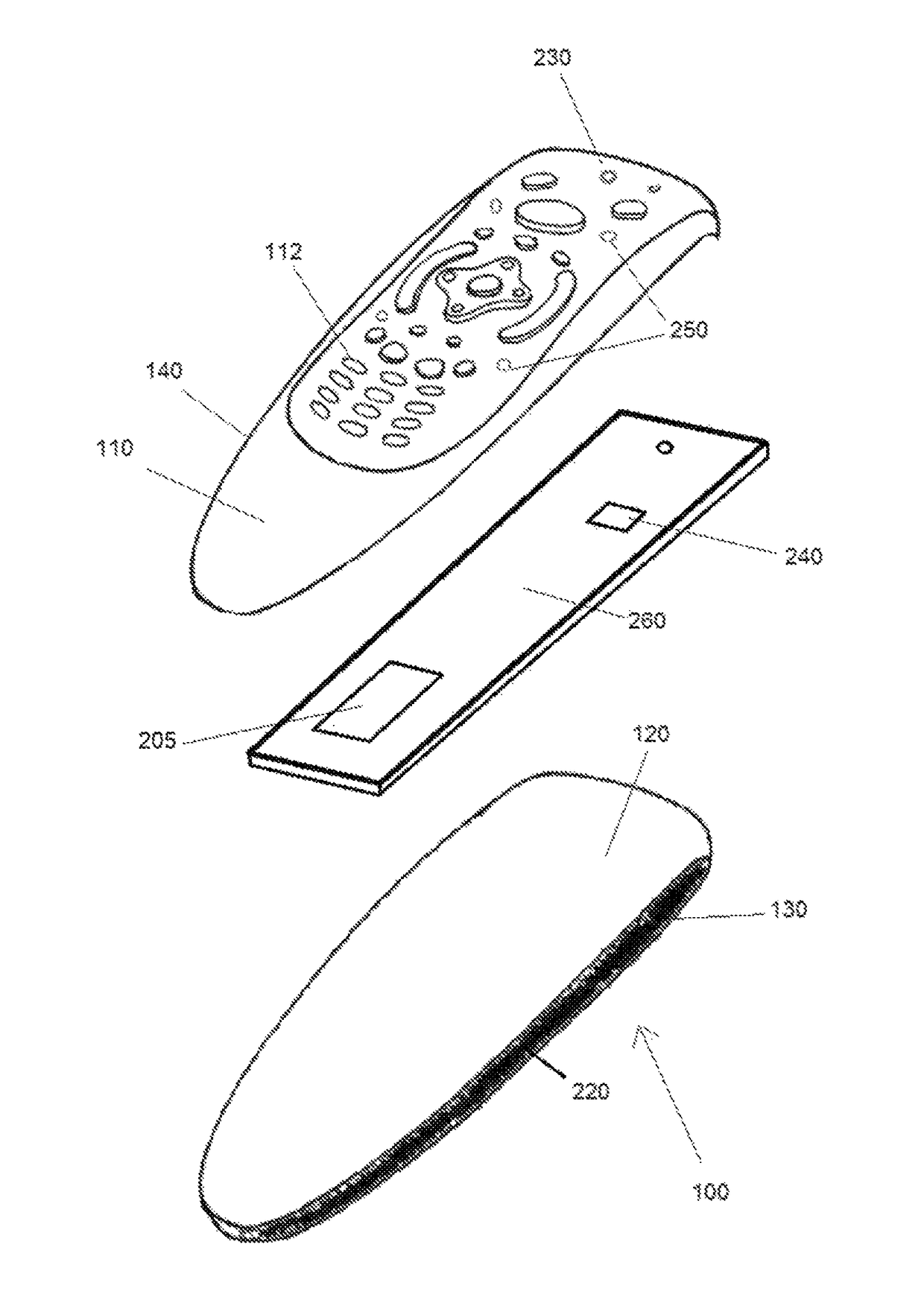
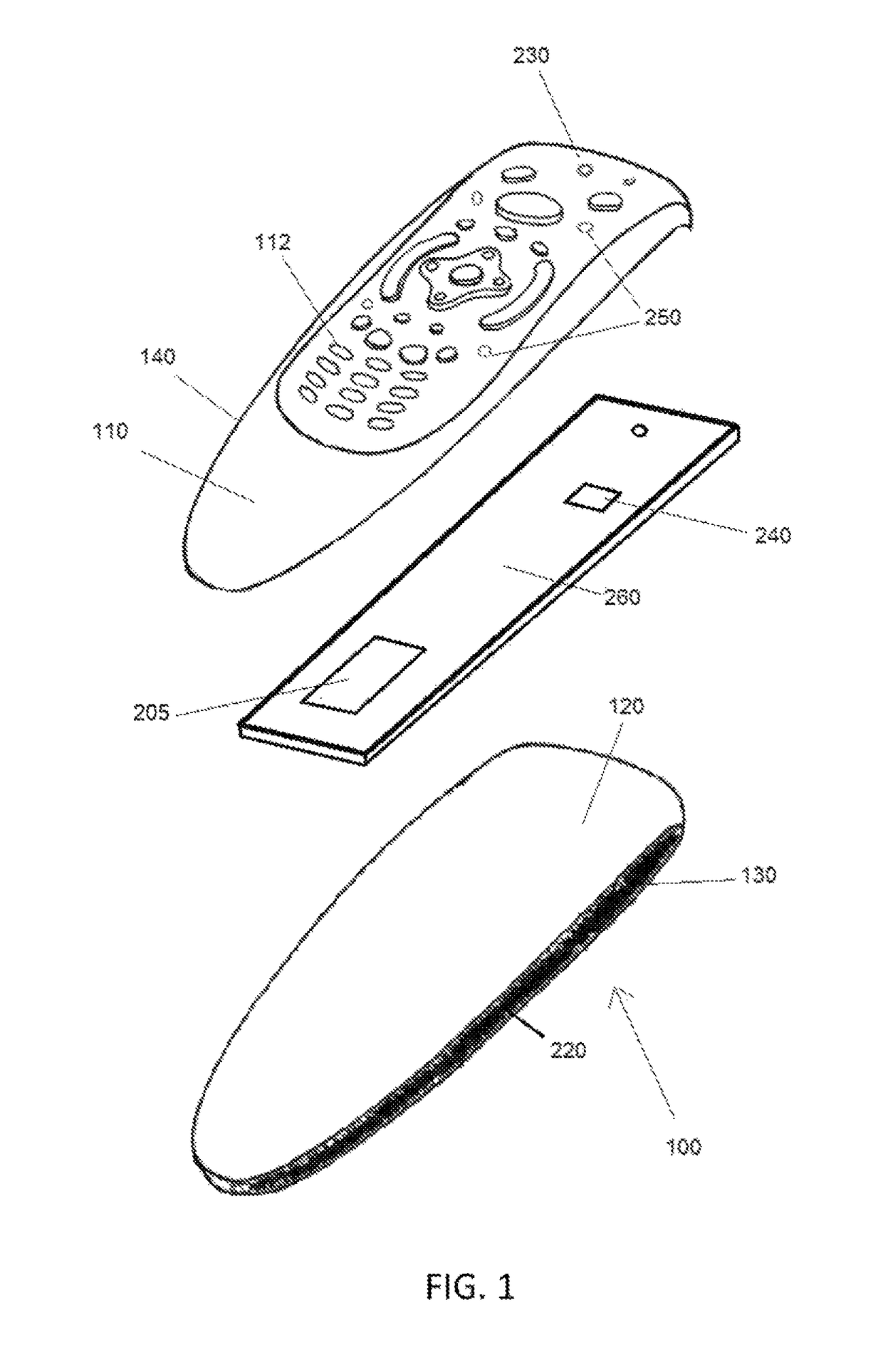
[0010]In a primary embodiment, the present invention is a remote controller with contact switch and remote control button illumination control. The remote controller has a front surface (110) having a plurality of remote control buttons (112) disposed thereon, and a back surface (120) having dials (261, 262) used to adjust the sensitivity of the controller. The front and back surfaces fit together to form an internal cavity. The remote controller has s first side (130) and a second side (140), a pair of contact strips (220) are disposed on the two sides which detect human capacitance when a user picks up the remote. A control board (260) is disposed within the cavity formed by the front surface (110) and the back surface (120), operatively connected to the control buttons.

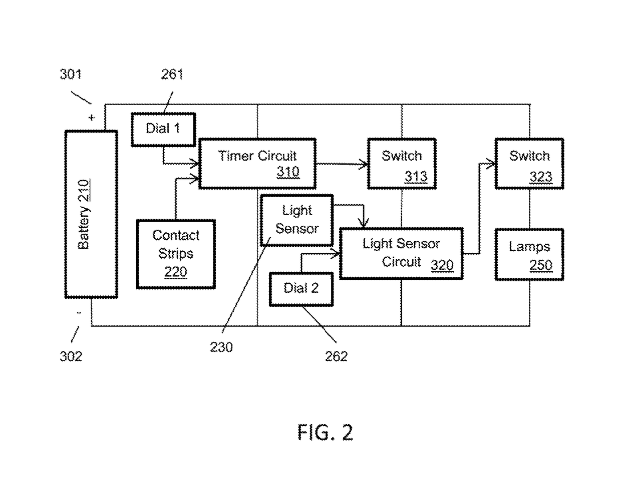
[0011]In a primary embodiment, the control board has electrical circuitry upon it used for the control features of the remote as well as the self-illuminating feature. The self-illuminating circuitry comprises a po...


PUM


Abstract

The present invention features a remote controller with touch switch and light sensor for key illumination control. When a user picks up the controller, a touch switch circuit is activated through means of contact strips built into the aides of the device. These strips sense a human body's capacitance. When this is sensed, an ambient light sensor is activated if the sensor detects low/no light conditions, which are adjustable to a user's preference. it activates a relay which then powers lamps to illuminate the remote controller. The lamps stay illuminated for an adjustable period of time based on user preference.

Description

CROSS REFERENCE[0001]This application claims priority to U.S. patent application Ser. No. 13 / 664,919 filed Oct. 31, 2012 as a continuation-in-part, the specification(s) of which is / are incorporated herein in their entirety by reference.FIELD OF THE INVENTION[0002]The present invention related to a remote controller, and more particularly to a remote controller with touch switch for illumination control.BACKGROUND OF THE INVENTION[0003]Lot of users feels the inconvenience of using remote controller in low / no light conditions. Some people may have to turn on a light in a room when other people may be sleeping. Presently phosphor illumination (glow in the dark) is being used. This needs light to charge, so if it is in long term darkness it would be ineffective. The glow in the dark illumination lasts for only a few minutes. Some remote controllers only illuminate buttons once a function key is pressed. The possibility of pressing an unwanted function key to activate the illumination is...

Claims


Application Information

Patent Timeline
IPC IPC(8): G08C17/02G06F3/044
CPCG08C17/02G06F3/044G08C2201/10G08C2201/30
Inventor GOODMAN, ROBERT C.
Owner GOODMAN ROBERT C
Why Eureka
Try Eureka