

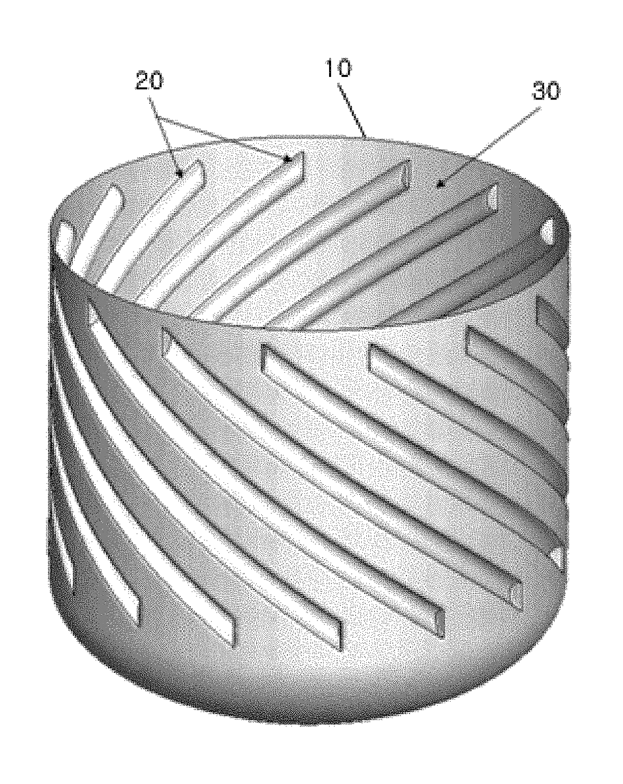
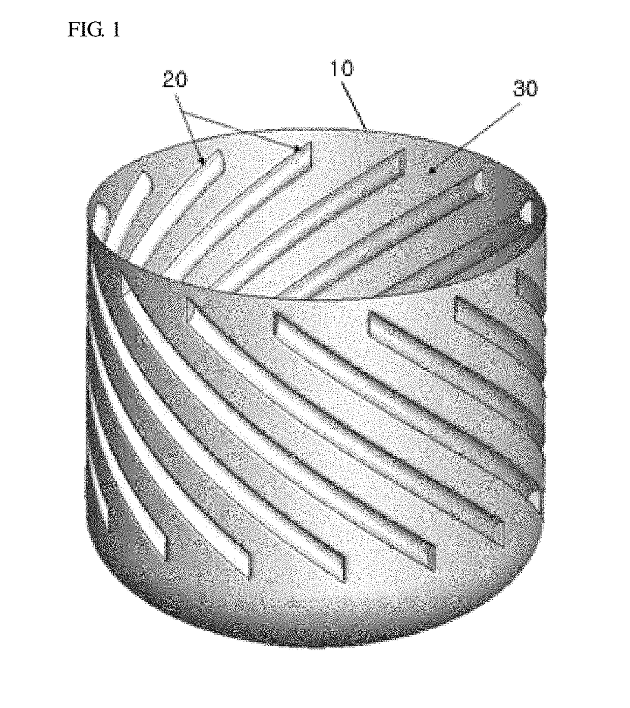
Stirrer having recesses formed inside container
a container and container technology, applied in the field of stirring machines, can solve problems such as irregular particle shape, and achieve the effects of reducing concentration deviation, and enhancing the degree of vertical mixing
- Summary
- Abstract
- Description
- Claims
- Application Information
AI Technical Summary
Benefits of technology
Problems solved by technology
Method used
Image

Examples
experimental example
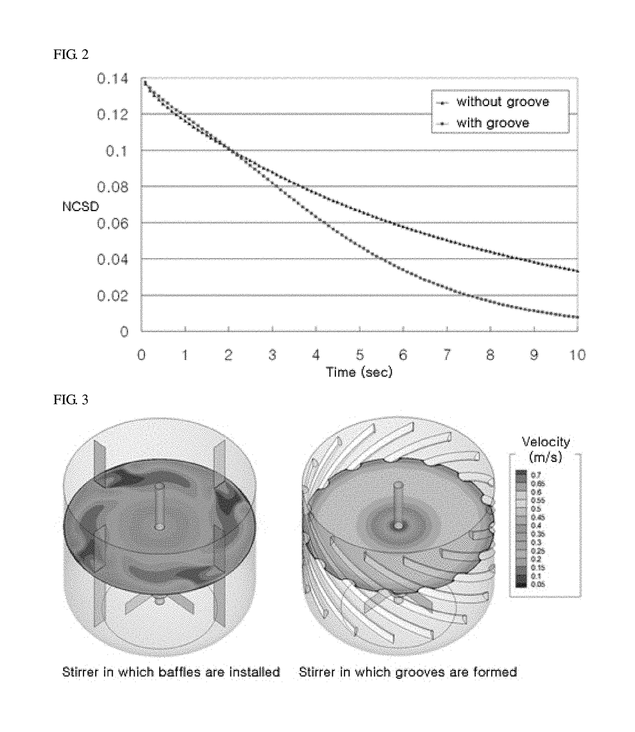
[0055]FIG. 2 is a graph for comparing a normalized concentration standard deviation (NCSD) of the stirrer (Comparative Example 1) on which no groove is formed with a normalized concentration standard deviation of the stirrer (Example) on which the grooves are formed, as time goes on.
[0056]The concentration deviation in the stirrer generated by mixing fluids, which were initially placed at the lower portion and the upper portion in the stirrer, as time goes on, may be calculated to judge the degree of vertical mixing. As can be seen from FIG. 2, as compared with the stirrer (Comparative Example 1) on which no groove was formed, the concentration deviation was rapidly reduced and the vertical mixing was thus enhanced in the stirrer (Example) having the grooves formed on the inner surface of the stirrer container.
[0057]FIG. 3 is a mimetic diagram for comparing velocity distribution of the stirrer (Comparative Example 2) having baffles provided therein with velocity distribution of the ...
PUM
| Property | Measurement | Unit |
|---|---|---|
| angle | aaaaa | aaaaa |
| angle | aaaaa | aaaaa |
| angle | aaaaa | aaaaa |
Abstract
Description
Claims
Application Information