Cargo handling device for a vehicle

a technology for handling devices and vehicles, applied in the directions of transportation and packaging, transportation items, loading/unloading vehicle arrangments, etc., can solve the problems of not being able to solve the needs of this art, and not being able to completely satisfy the requirements of a complete solution

Active Publication Date: 2017-07-25
NEAL BRYANT D
View PDF37 Cites 12 Cited by
  • Summary
  • Abstract
  • Description
  • Claims
  • Application Information

AI Technical Summary

Benefits of technology

[0038]The present invention is defined by the appended claims with specific embodiments being shown in the attached drawings. For the purpose of summarizing the invention, the invention relates to an improved cargo handling device for a vehicle. The cargo handling device comprises a base extending between a lower end and an upper end. The lower end of the base is coupled to the cargo surface. A lower track extends between a proximal end and a distal end. The proximal end of the lower track is coupled to the base. An upper track extends between a proximal end and a distal end. The proximal end of the upper track is coupled to the base. A traveler has a lower track receiver and an upper track receiver. The lower track receiver of the traveler slidably engages the lower track between the proximal end and the distal end of the lower track. The upper track receiver of the traveler slidably engages the upper track between the proximal end and the distal end of the upper track. A storage unit has a lower track receiver and an upper track receiver and extends between a proximal end and a distal end. The lower track receiver of the storage unit slidably engages the lower track between the proximal end and the distal end of the lower track. The

Problems solved by technology

None, however completely satisfies the requirements for a complete solution to the aforestated problem.
Although the aforementioned prior art

Method used


Image

  • Cargo handling device for a vehicle
  • Cargo handling device for a vehicle
  • Cargo handling device for a vehicle

Examples


Embodiment Construction

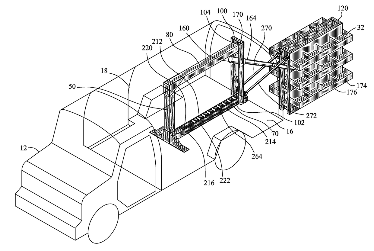
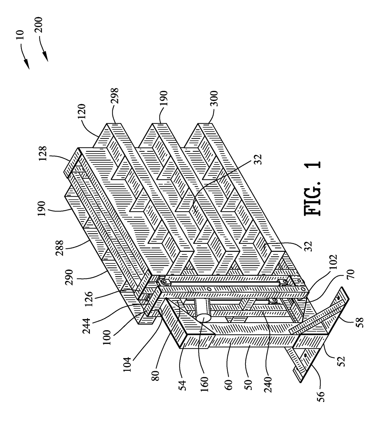
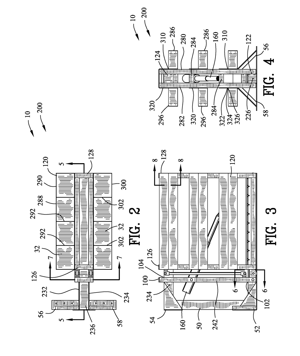
[0078]FIGS. 1-31 illustrate a cargo handling device 10 utilized with a vehicle 12. The vehicle 12 is shown as a van 14, however the vehicle 12 may include but not limited to a truck, trailer, mini-van, all terrain vehicle, automobile or other vehicles. The vehicle 12 has a cargo surface 16, a first cargo wall 18, a second cargo wall 20 and a cargo ceiling 22. The cargo surface 16, the cargo first wall 18, the second cargo wall 20 and the cargo ceiling 22 define a cargo area 24. The vehicle 12 includes a rear cargo aperture 26 for accessing the cargo area 24. The rear cargo aperture 26 may include a first door 28 and a second door 30 for closing the rear cargo aperture 24. The vehicle 12 transports a cargo 32 over a surface.

[0079]The cargo handling device 10 comprises a base 50 extending between a lower end 52 and an upper end 54. The lower end 52 of the base 50 is coupled to the cargo surface 16. The base 50 may further include a primary base plate 56 and a secondary base plate 58 c...


PUM


Abstract

A cargo handling device is disclosed for a vehicle. The cargo handling device comprises a base and a lower track. A traveler and a storage unit slidably engage the lower track between a proximal end and a distal end. A linear actuator displaces the traveler between the proximal end and the distal end. A telescoping actuator is pivotably coupled to the traveler and the storage unit. A contracted length in the telescoping actuator maintains the traveler abutting the storage unit during displacement of the traveler between the proximal end and the distal end. An extended length in the telescoping actuator displaces the storage unit from the traveler upon the traveler positioned at the distal end. The extended length defines a horizontal displacement and a vertical displacement of the storage unit from the traveler for positioning the storage unit adjacent the surface.

Description

CROSS-REFERENCE TO RELATED APPLICATIONS[0001]This application claims benefit of U.S. Patent Provisional application Ser. No. 62 / 217,134 filed Sep. 11, 2015. All subject matter set forth in provisional application Ser. No. 62 / 217,134 is hereby incorporated by reference into the present application as if fully set forth herein.BACKGROUND OF THE INVENTION[0002]Field of the Invention[0003]This invention relates to cargo handling and more particularly to a cargo handling device for a vehicle.[0004]Background of the Invention[0005]Part and equipment storage in vans and small trucks has produced a large number and variety of vehicle mounted racks. These racks have provided a great convenience to the user by keeping parts and equipment organized and readily accessible. The necessity to repeatedly enter and exit the vehicle led to the development of racks and shelving units that were removable from within the vehicle, for use at ground level. These racks generally contained relatively small ...

Claims


Application Information

Patent Timeline
IPC IPC(8): B60P1/44B62D33/04
CPCB60P1/4442B60P1/4492B62D33/04B60P3/007
Inventor NEAL, BRYANT D.
Owner NEAL BRYANT D
Why Eureka
Try Eureka