
Gaze direction measuring method and gaze direction measuring device

a technology of measuring device and direction, applied in the field of gaze direction measuring method, can solve the problems of difficult texture paste onto the 3-dimensional model, significant deformation of the accuracy of face direction measurement and gaze direction measurement, and large influence of conventional methods, so as to reduce the effect of expression change, accurate measurement, and high accuracy of gaze direction measuremen

Inactive Publication Date: 2009-04-30
HITACHI LTD
View PDF3 Cites 58 Cited by
  • Summary
  • Abstract
  • Description
  • Claims
  • Application Information

AI Technical Summary

Benefits of technology

[0017]In the vertical displacement amount measurements, it is possible to reduce the affects of the expression change and accurately perform the measurements by using the displacement from the shoulder position and the positions of the inner and the outer corner of the eye.
[0019]That is, the advantage obtained by the representative invention is that it is possible to realize a highly accurate gaze direction measuring method which does not require calibration in advance and is hardly affected by a person's expression change.

Problems solved by technology

Thus, the conventional method has a problem that it is necessary to build a 3-dimensional model for each of persons in advance for measurement in the vertical direction.
When the face is directed to the left or right and no characteristic point appears on the image, it is difficult to paste the texture onto the 3-dimensional model.
If a measurement is performed by using an incorrect model, accuracy of the face direction measurement and the gaze direction measurement is significantly degraded.
Moreover, there is a problem that the conventional method is greatly affected by an expression change.
In this case, even if the 3-dimensional model is rotated to perform a comparison process, the similarity is lost and a large error is caused in the measurement result.

Method used


Image

  • Gaze direction measuring method and gaze direction measuring device
  • Gaze direction measuring method and gaze direction measuring device
  • Gaze direction measuring method and gaze direction measuring device

Examples


embodiment 1

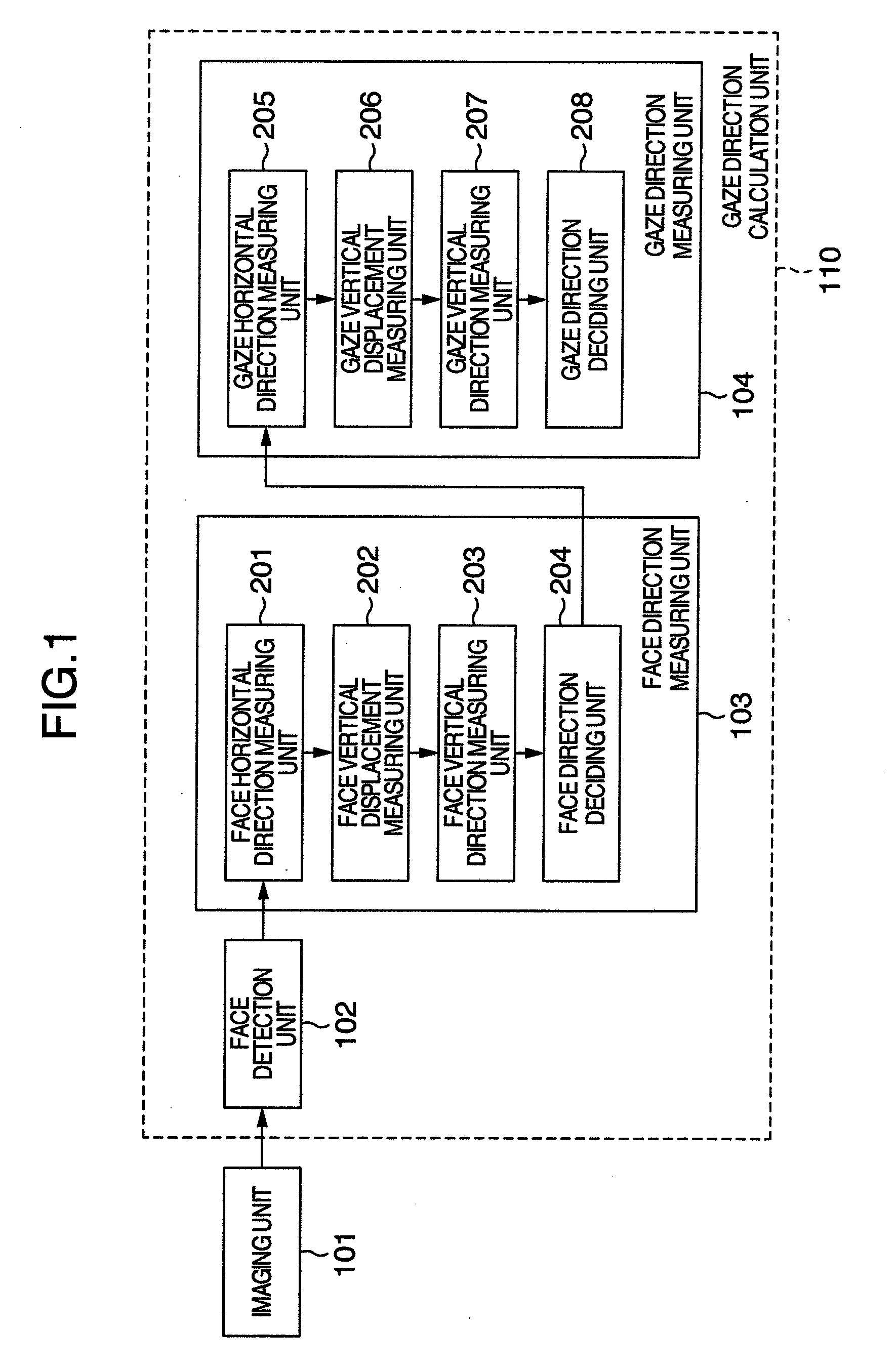
[0038]Referring to FIG. 1, explanation will be given on a configuration of a gaze direction measuring device according to a first embodiment of the present invention.

[0039]In FIG. 1, the gaze direction measuring device includes an imaging unit 101, a face detection unit 102, a face direction measuring unit 103, and a gaze direction measuring unit 104. The face detection unit 102, the face direction measuring unit 103, and the gaze direction measuring unit 104 constitute a gaze direction calculation unit 110.

[0040]The face direction measuring unit 103 is formed by a face horizontal direction measuring unit 201, a face vertical displacement measuring unit 202, a face vertical direction measuring unit 203, and a face direction deciding unit 204.

[0041]The gaze direction measuring unit 104 is formed by a gaze horizontal direction measuring unit 205, a gaze vertical displacement measuring unit 206, a gaze vertical direction measuring unit 207, and a gaze direction deciding unit 208.

[0042]...

embodiment 2

[0094]Referring to FIG. 13, explanation will be given on the configuration of a gaze direction measuring device according to a second embodiment of the present invention. FIG. 13 is a block diagram explaining the configuration of the gaze direction measuring device according to the second embodiment of the present invention.

[0095]In FIG. 13, the gaze direction measuring device 1300 includes an image input unit 1301, an image memory 1302, a CPU 1303, a RAM 1304, a ROM 1305, a measurement result recording unit 1306, an interface 1307, and an output device 1308.

[0096]The gaze direction measuring device 1300 of the present embodiment measures a gaze direction of a person in an image captured by a camera as the imaging unit 101. The CPU 1303 in the gaze direction measuring device 1300 of the present embodiment corresponds to the gaze direction calculation unit 110 of the first embodiment shown in FIG. 1 and executes various calculation processes of the gaze direction calculation unit 110...

embodiment 3

[0100]Referring to FIG. 14, explanation will be given on a configuration of a gaze direction measuring device according to a third embodiment of the present invention. FIG. 14 is a block diagram showing the configuration of the gaze direction measuring device according to the third embodiment of the present invention.

[0101]As compared to the first embodiment, the third embodiment further includes an attention judgment unit 1401 as an input and a model calibration unit 1402. For example, the model calibration unit 1402 automatically calibrates parameters such as a face reference position calculation constant d in the face vertical direction measurement for each of measurement objects, thereby enabling a more accurate gaze direction measurement.

[0102]The attention judgment unit 1401 is formed, for example, by an LED light source projector and an infrared camera. When the gaze is directed to the attention judgment unit 1401, the gaze can be detected. If the positional relationship betw...


PUM


Abstract

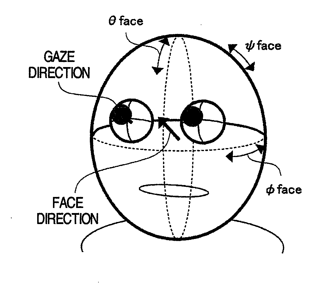
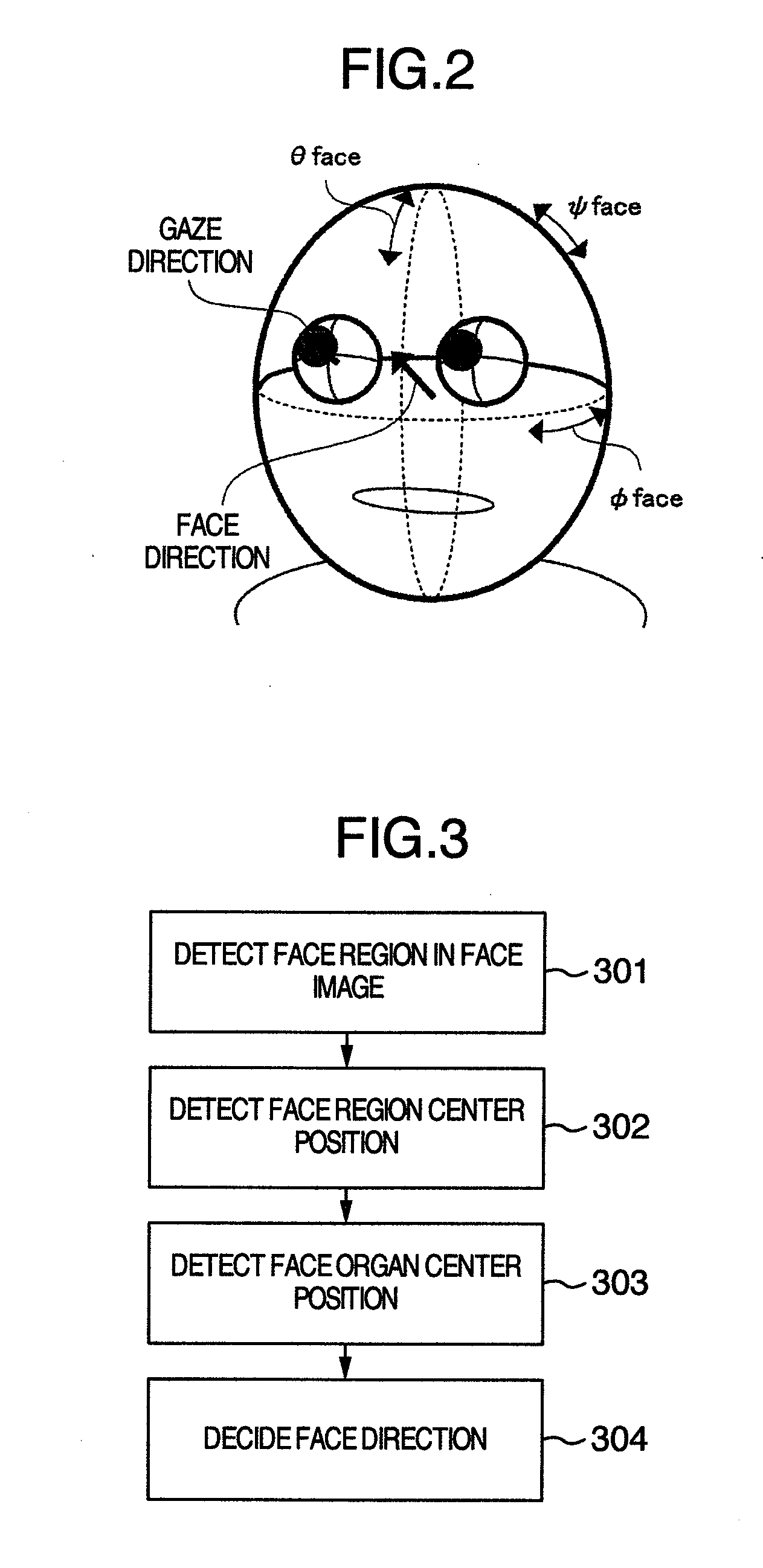
A face horizontal direction measuring unit measures the angle of the face horizontal direction for a face image obtained by an imaging unit. By using information on the radius of the head and information on the shoulder position of the person obtained by the aforementioned measurement, a face vertical displacement measuring unit measures a face displacement in the vertical direction not affected by a head posture. According to the obtained displacement, the face angle in the vertical direction is decided. By using the obtained face direction, the angle of the gaze in the horizontal direction and the eyeball radius are measured. Further, a gaze vertical displacement measuring unit is provided for which measuring the pupil center position against the eyeball center position as the gaze displacement in the vertical direction. This displacement amount is used to measure the gaze angle in the vertical direction.

Description

INCORPORATION BY REFERENCE[0001]The present application claims priority from Japanese application JP2007-277670 filed on Oct. 25, 2007, the content of which is hereby incorporated by reference into this application.BACKGROUND OF THE INVENTION[0002]1. Field of the Invention[0003]The present invention relates to a gaze direction measuring method for measuring a gaze direction, i.e., into which direction (degrees) a person captured in an image looks and a gaze direction measuring device for executing the method and in particular, to a technique which can effectively be applied to a vertical direction measuring method.[0004]2. Description of the Related Art[0005]By measuring a gaze direction of a person in an image, it is possible to estimate his / her object of interest and psychological state. As a method for measuring a gaze direction of a person, there has been a method for separately measuring a face direction and an eye direction and synthesizing them so as to measure a gaze directi...

Claims


Application Information

Patent Timeline
IPC IPC(8): A61B3/113
CPCA61B3/113A61B5/1114A61B5/1128G06T2207/30201G06K9/00248G06T7/0046G06T2207/30041G06F3/013G06T7/75G06V40/165G06V40/193
Inventor YOSHINAGA, TOMOAKINAGAYA, SHIGEKISAYAMA, CHIHARU
Owner HITACHI LTD
Learn More