
Vehicle wash component

a technology for washing components and vehicles, applied in vehicle maintenance, vehicle cleaning, transportation and packaging, etc., can solve the problems of known limitations, and reduced contact between the media elements of the rotary side brush and the large angled side surface of the vehicl

Active Publication Date: 2017-07-25
PISTON OPW INC
View PDF10 Cites 1 Cited by
  • Summary
  • Abstract
  • Description
  • Claims
  • Application Information

AI Technical Summary

Benefits of technology

This patent describes a new vehicle wash component that can clean vehicles of different sizes and shapes. It also improves cleaning for vehicles with different contours and shapes. Additionally, it generates less noise than existing components, saves energy, and provides a more enjoyable experience for customers.

Problems solved by technology

While these rotary brushes work satisfactorily, they have known limitations.
However, current rotary brushes have cleaning limitations for vehicles with large angled side surfaces.
This is because contact between the media elements of the rotary side brush and the large angled side surface of the vehicle is decreased due to the fact that the media elements do not extend into the vehicle treatment area a sufficient distance to contact the entirety of the angled side surface.
As such, the quality of the cleaning is significantly reduced.
Thus, while these tilted rotary brushes provide improved cleaning on the upper angled surfaces of the vehicle exterior, the quality of cleaning on the lower vertical surfaces of the vehicle is known to suffer.
In other words, while the upper media elements engage the angled surface of the vehicle exterior, the lower media elements often do not sufficiently engage the lower vertical surfaces to provide the desired cleaning.
Another issue with current vehicle wash components is their inability to provide consistent cleaning for all vehicle widths.
For example, while current vehicle wash components provide acceptable cleaning for some vehicle sizes and widths, they often are unable to provide the same cleaning of other vehicle sizes.

Method used


Image

  • Vehicle wash component
  • Vehicle wash component
  • Vehicle wash component

Examples


Embodiment Construction

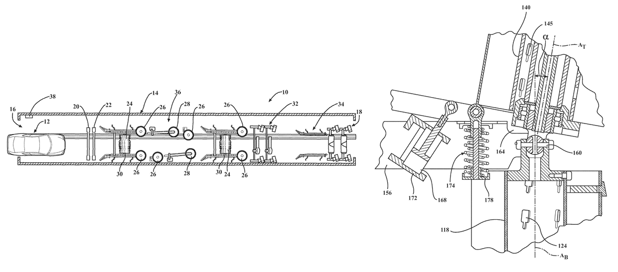
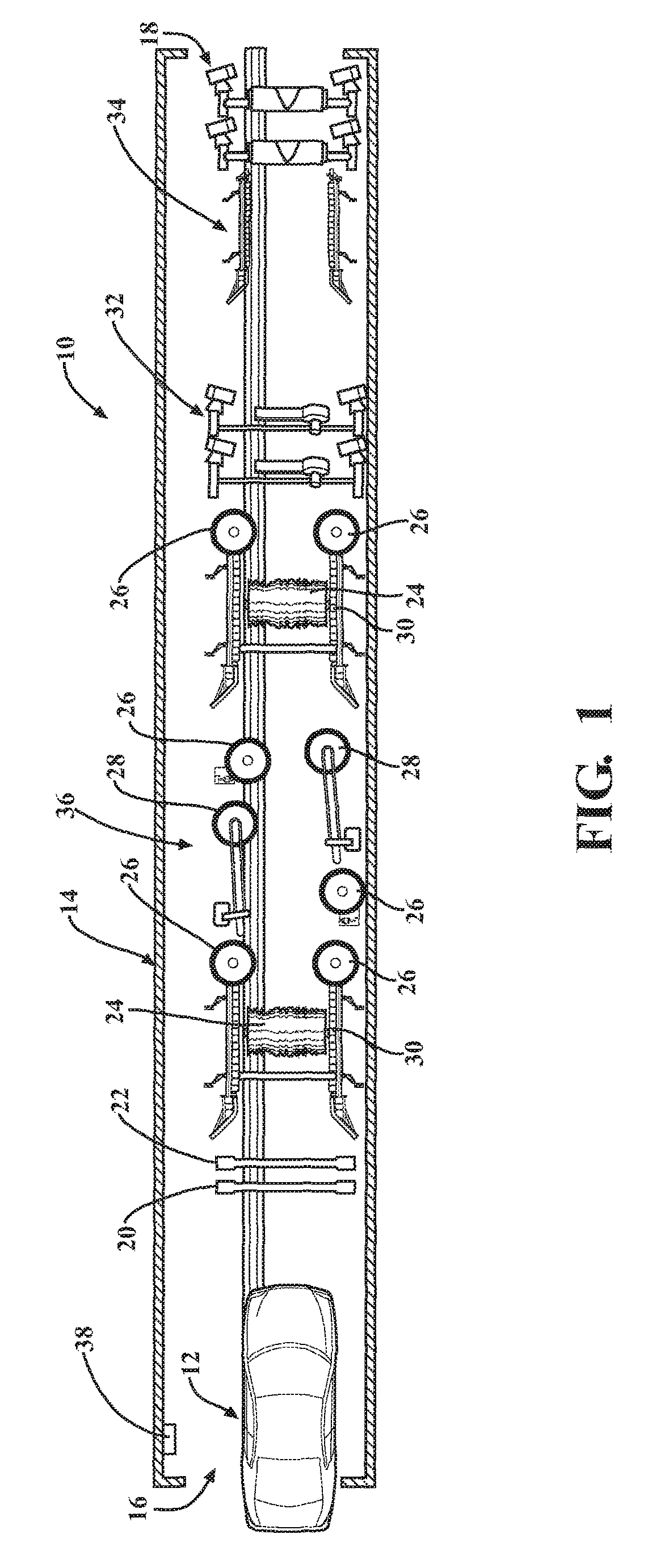
[0035]According to an aspect, the present disclosure relates to a vehicle wash system 10. As shown in FIG. 1, the system 10 may be configured as a tunnel car wash, where a vehicle 12 is conveyed through the wash process by a conveyor or the like as is known in the art. Alternatively, the vehicle wash system 10 may be configured as a roll-over type where the vehicle 12 remains stationary and the components move with respect to the vehicle 12. Other suitable wash processes and systems may also be employed. According to an aspect, the vehicle wash system 10 may be housed within a vehicle wash facility 14 having an entrance end 16 where a vehicle enters and an exit end 18 where the vehicle leaves. According to a further aspect, the vehicle wash system 10 may also include a variety of vehicle wash components that engage and / or treat the exterior of the vehicle 12 as it passes through the vehicle wash facility 14 to effectuate the vehicle wash process.

[0036]According to an aspect, the veh...


PUM


Abstract

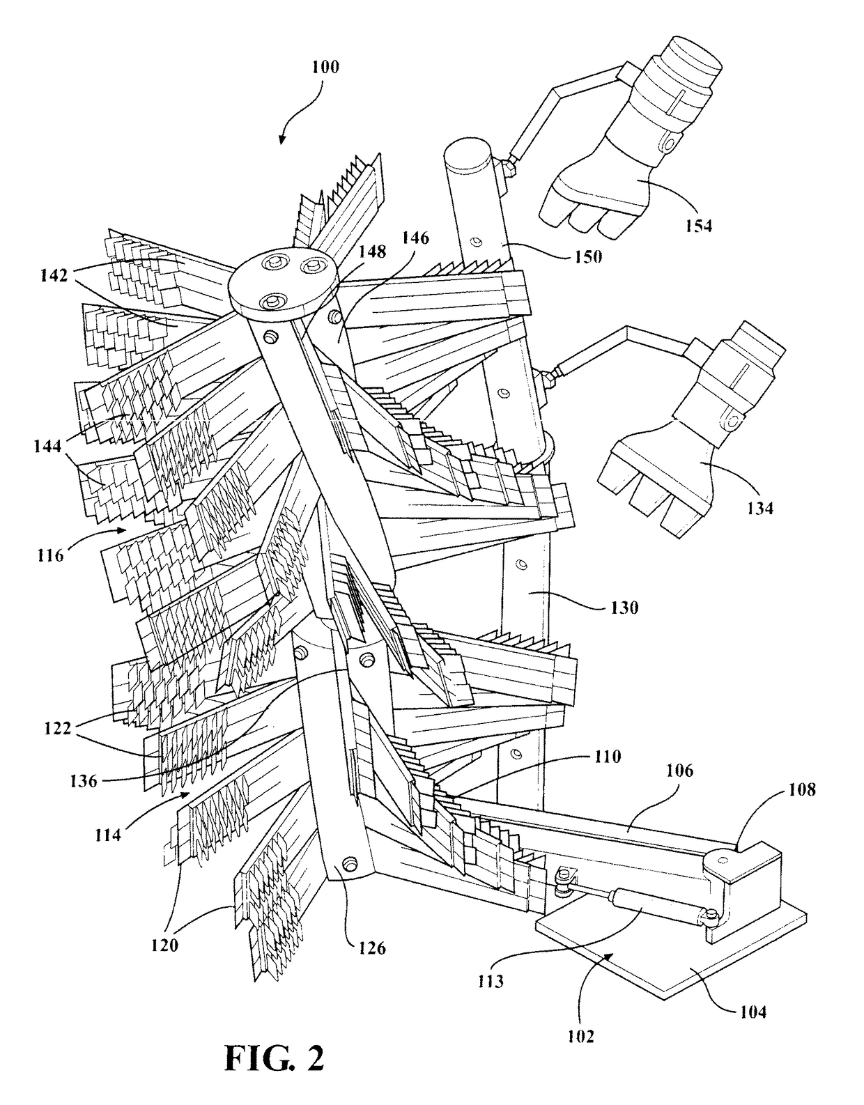
A vehicle wash component includes a hub portion with a first hub section and a second hub section. The first hub section includes a first distal end and a first proximate end opposite the first distal end. The first hub section defines a first axis of rotation. The second hub section includes a second distal end and a second proximate end opposite the second distal end. The second hub section defines a second axis of rotation. A connector device rotatably couples the first hub section to the second hub section. An actuator is in communication with the first hub section to effectuate movement of the first distal end between a retracted position and an extended position. In the retracted position, the first axis of rotation and the second axis of rotation are parallel. In the extended position, the first axis of rotation is at a non-90 angle with respect to the second axis of rotation.

Description

CROSS-REFERENCE TO RELATED APPLICATIONS[0001]The present application is a continuation in part of U.S. patent application Ser. No. 13 / 668,029, entitled “An Improved Media Element for a Vehicle Wash Component”, filed Nov. 2, 2012, now U.S. Pat. No. 9,199,613; which is a continuation in part of U.S. patent application Ser. No. 13 / 668,058, entitled “Vehicle Wash Component”, filed Nov. 2, 2012, now U.S. Pat. No. 8,990,993; which is a continuation in part of U.S. patent application Ser. No. 13 / 668,121, entitled “Hub for a Vehicle Wash Component Having an Arcuate Pattern of Media Elements”, filed Nov. 2, 2012, now U.S. Pat. No. 9,248,809; which is a continuation in part of U.S. patent application Ser. No. 13 / 668,093, entitled “Illuminated Hub for a Vehicle Wash Component”, filed Nov. 2, 2012, now U.S. Pat. No. 8,819,887, all of which claim priority to U.S. Provisional Patent Application Ser. No. 61 / 554,559, entitled “Car Wash Implement and Splayable Foam Plastic Element for Use in Constru...

Claims


Application Information

Patent Timeline
Patent Type & Authority Patents(United States)
IPC IPC(8): B60S3/06A46B13/00A46B5/00
CPCB60S3/06A46B5/00A46B5/005A46B5/0033A46B5/0041A46B5/0075A46B13/001B60S3/063A46B2200/3046A46B13/005A46B2200/30B60S3/066
Inventor BELANGER, MICHAEL J.WEYANDT, THOMAS E.KOTRYCH, JERRY A.TURNER, BARRY S.
Owner PISTON OPW INC
Learn More