Supercharge Your Innovation With Domain-Expert AI Agents!

Captured image compression transmission method and captured image compression transmission system

a transmission system and image compression technology, applied in the field of captured image compression transmission methods and captured image compression transmission systems, can solve the problems of large size of captured image data, finite wireless transmission capacity, and long transmission time, and achieve the effect of reducing the amount of transmission data

Active Publication Date: 2017-08-15
NEC CORP
View PDF13 Cites 0 Cited by
  • Summary
  • Abstract
  • Description
  • Claims
  • Application Information

AI Technical Summary

Benefits of technology

The present invention reduces the amount of transmission data by creating differential data by specifying a reference image in a stepwise manner. This is useful when capturing various conditions.

Problems solved by technology

When image capturing is continually performed in a flying vehicle, the size of captured image data becomes very large.
However, because the capacity of wireless transmission is finite, a long transmission time is necessary in a case of a large data size.

Method used


Image

  • Captured image compression transmission method and captured image compression transmission system
  • Captured image compression transmission method and captured image compression transmission system
  • Captured image compression transmission method and captured image compression transmission system

Examples


first exemplary embodiment

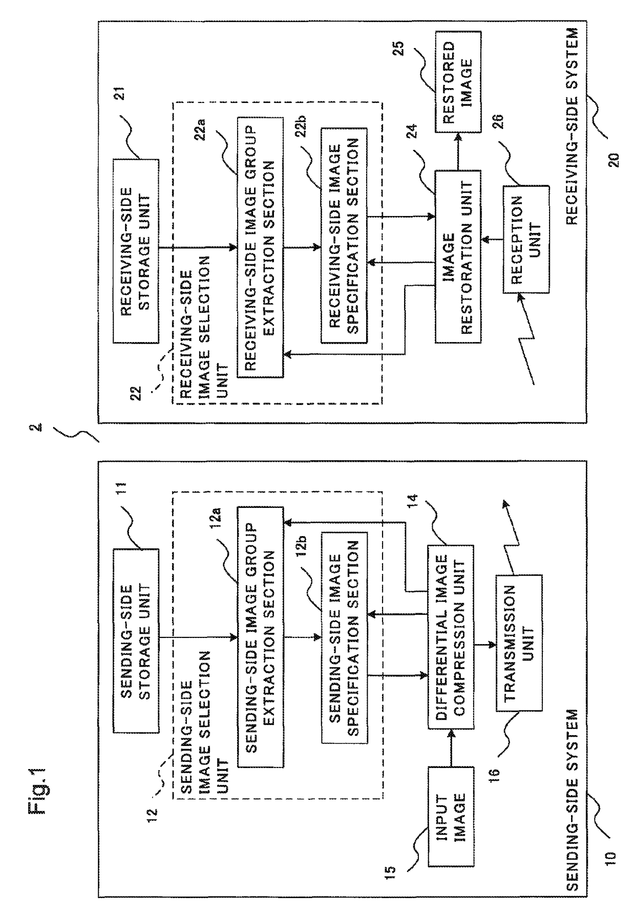
[0019]A first exemplary embodiment of the present invention will be described below. FIG. 1 is a block diagram of a captured image compression transmission system 2 according to the present exemplary embodiment. The captured image compression transmission system 2 is composed of a sending-side system 10 arranged at the sending side and a receiving-side system 20 arranged at the receiving side.

[0020]The sending-side system 10 comprises a sending-side storage unit 11, a sending-side image selection unit 12, a differential image compression unit 14 and a transmission unit 16. The sending-side image selection unit 12 includes a sending-side image group extraction section 12a and a sending-side image specification section 12b. The receiving-side system 20 comprises a receiving-side storage unit 21, a receiving-side image selection unit 22, an image restoration unit 24 and a reception unit 26. The receiving-side image selection unit 22 includes a receiving-side image group extraction sect...

second exemplary embodiment

[0059]Next, a second exemplary embodiment of the present invention will be described. Here, for the same configuration as that in the first exemplary embodiment, the same sign is used and its description will be properly omitted.

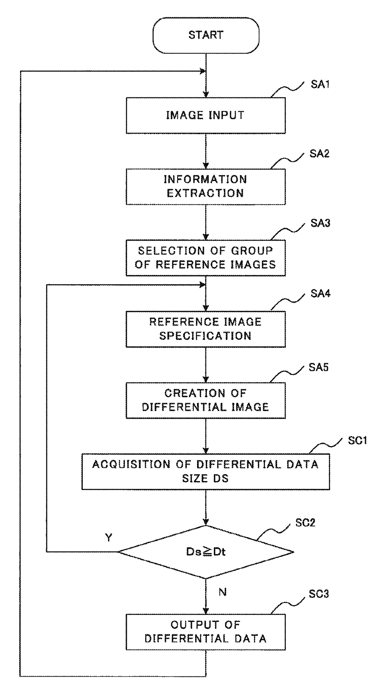
[0060]In the first exemplary embodiment, a plurality of reference images corresponding to various kinds of capturing information are stored in advance. Then, one specific reference image is selected from among the plurality of reference images, and differential data is created with respect to it. In that case, determination of whether or not a selected specific reference image is the most appropriate image to minimize the size of differential data is not performed. In this respect, the present exemplary embodiment is configured such that whether the data size of created differential data is too large or not is determined so as to obtain differential data with the smallest size.

[0061]FIG. 4 is a flow chart showing a process performed in such a configuration. ...


PUM


Abstract

Provided is a captured image compression transmission system comprising: a sending-side system which compresses an input image and sends the compressed image data; and a receiving-side system which restores the input image on the basis of the image data received from the sending-side system; wherein the sending-side system comprises: a sending-side storage unit which stores a plurality of reference images; a sending-side image selection unit which, in accordance with the degree of priority of information included in capturing information attached to an input image, selects reference images corresponding to the information in a stepwise manner from the sending-side storage unit, and thereby specifies one reference image; a differential image compression unit which acquires differential data between the reference image specified by the sending-side image selection unit and the input image, and compresses the differential data; and a transmission unit which sends the compressed differential data to the receiving-side system.

Description

CROSS-REFERENCE TO RELATED APPLICATIONS[0001]This application is a national stage application of International Application No. PCT / JP2012 / 071742 entitled “Captured Image Compression and Transmission Method and Captured Image Compression and Transmission System,” filed on Aug. 22, 2012, which claims the benefit of the priority of Japanese Patent Application No. 2011-190608, filed on Sep. 1, 2011, the disclosures of each of which are hereby incorporated by reference in their entirety.TECHNICAL FIELD[0002]The present invention relates to a captured image compression transmission method and a captured image compression transmission system, both for transmission of image data captured by a flying vehicle.BACKGROUND ART[0003]Today, it is popular to send image data captured by a flying vehicle, such as an aircraft and a satellite, to a ground station or the like, for the purpose of performing a process of analyzing the image data or the like on the ground.[0004]When image capturing is cont...

Claims


Application Information

Patent Timeline
Patent Type & Authority Patents(United States)
IPC IPC(8): H04N19/503H04N19/507
CPCH04N19/503H04N19/507
Inventor NAKAMURA, YOICHI
Owner NEC CORP
Features
  • R&D
  • Intellectual Property
  • Life Sciences
  • Materials
  • Tech Scout
  • Unparalleled Data Quality
  • Higher Quality Content
  • 60% Fewer Hallucinations
Learn More