Printing head and ink-jet printing device

a printing head and inkjet technology, applied in printing and other directions, can solve the problems of increasing and increasing serious and achieve the effect of reducing the interference between the nozzles caused by the same piezoelectric material and improving the quality of printing

Active Publication Date: 2017-08-22
BOE TECH GRP CO LTD
View PDF15 Cites 0 Cited by
  • Summary
  • Abstract
  • Description
  • Claims
  • Application Information

AI Technical Summary

Benefits of technology

[0007]In the prior art, there are two methods for reducing the interference. The first one is: changing the structure of the ink intake channel of the nozzle portion such that two adjacent spacers for separating adjacent nozzles are arranged to have different lengths, that is, the portion of the diversion trench close to the nozzle is different from that connected to the common trench so that the interference between the adjacent nozzles is reduced; and the second one is: optimizing a circuit signal to eliminate or reduce the generation of the interference, that is, at the same time of jetting ink from one nozzle, a corresponding reverse compensation drive signal is applied to nozzles adjacent to the nozzle, to offset the interference to the adjacent nozzles.
[0008]Inventors of the present invention propose a method different from the aforementioned methods for reducing the interference.
[0021]The nozzles are arranged on a plurality of sub-heads, so that, in the case of a same pixel pitch, the number of the nozzles in each of the sub-heads is relatively small, and the spacing of the diversion trenches corresponding to the respective nozzles is thus relatively large. As a result, the interference among the nozzles caused by the same piezoelectric material is reduced, and the quality of printing is thus improved.

Problems solved by technology

With the increase of the density of the nozzles, such interference will be more and more serious.

Method used


Image

  • Printing head and ink-jet printing device
  • Printing head and ink-jet printing device
  • Printing head and ink-jet printing device

Examples


Embodiment Construction

[0038]The exemplary embodiments shown in the accompanying drawings will be described in detail herein. In the accompanying drawings, dimensions and relative dimensions of each layer and each region will be exaggerated for the purpose of clarity. The same reference numbers always designate the same elements. Implementations to be described in the following exemplary embodiments do not represent all the implementations consistent with the present invention. Instead, they are only examples of devices or methods consistent with some aspects of the present invention as described in detail in the attached claims.

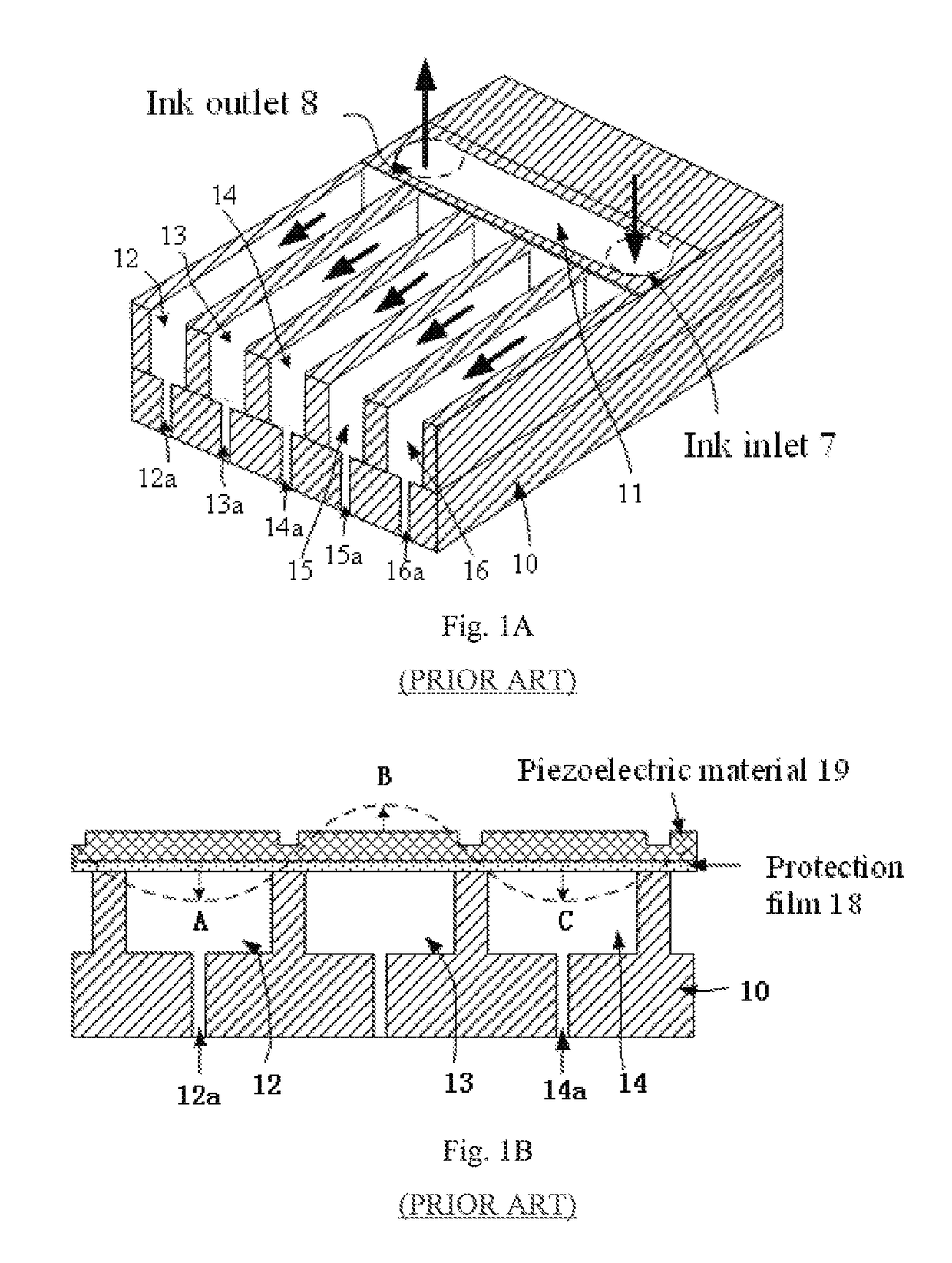
[0039]The printing head may mainly include a piezoelectric head and a bubble head. The embodiments of the present invention will be described by taking a piezoelectric head as an example. However, those skilled in the art can readily apply the concept of the present invention to a bubble head upon reading the specification of the present invention.

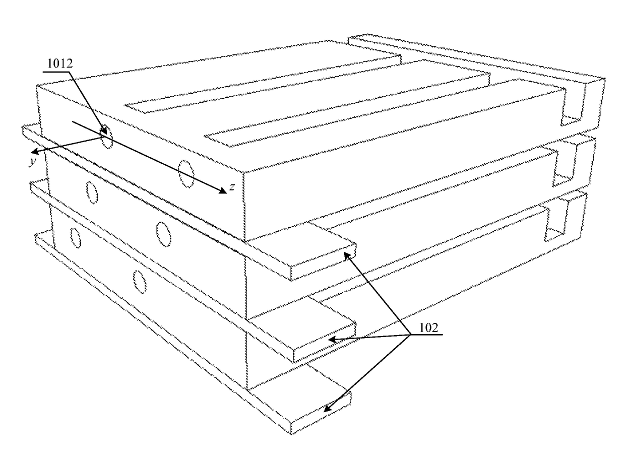
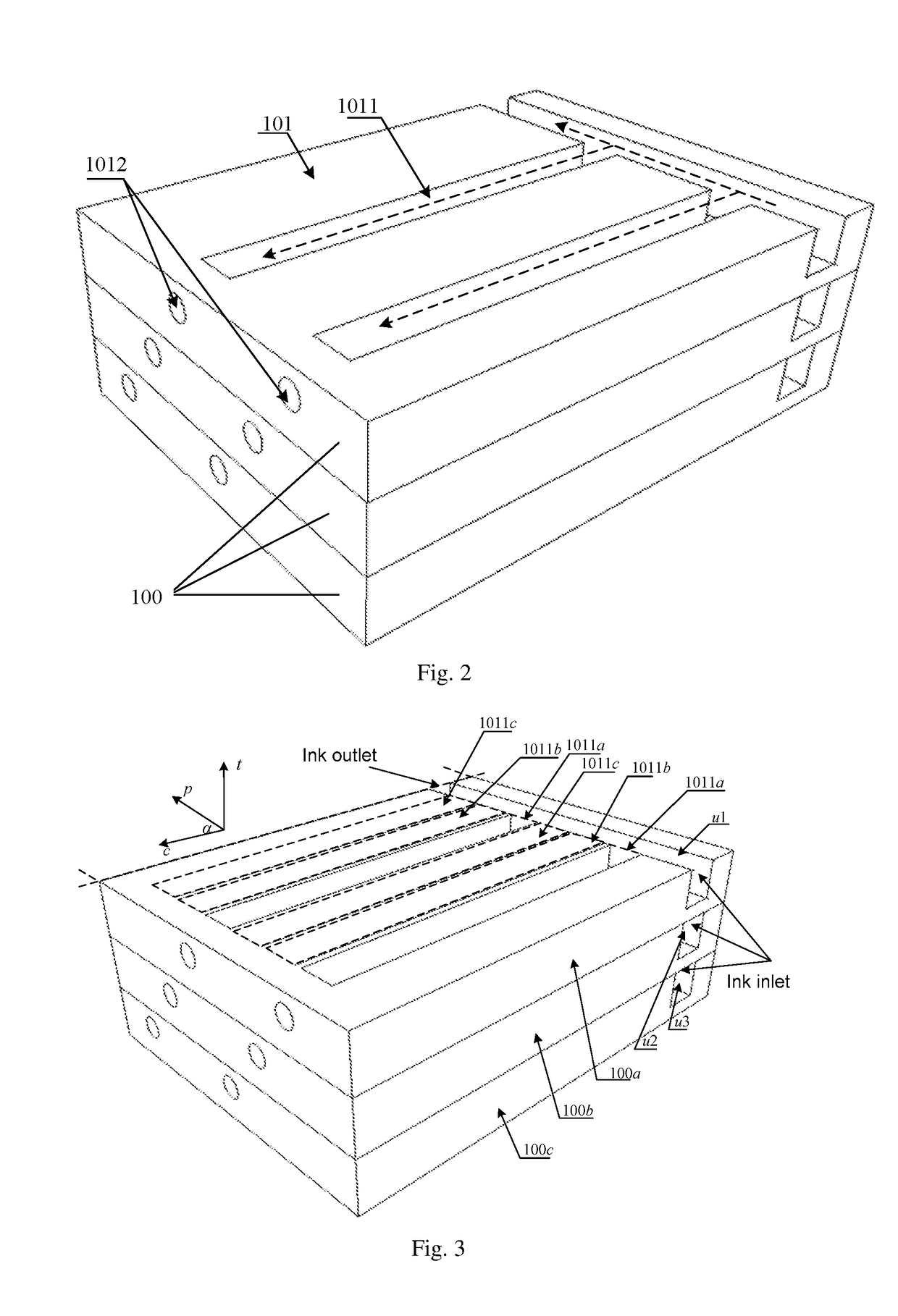
[0040]FIG. 2 is a schematic struc...


PUM


Abstract

The present invention provides a printing head comprising a plurality of sub-heads each comprising a base and a plurality of diversion trenches provided in the base, and one end of each of the diversion trenches is connected to one of nozzles of the sub-head. Projections of all the diversion trenches on a first plane in a first projection direction are arranged at an equal interval, the first plane is a plane defined by an arrangement direction and a length direction of the diversion trenches in the sub-head, and the first projection direction is a moving direction of the printing head with respect to a printing surface during printing. The spacing of the diversion trenches in each of the sub-heads is greater than that of the projections of all the diversion trenches in the first plane on the first projection direction.

Description

CROSS REFERENCE[0001]This is a National Phase Application filed under 35 U.S.C. 371 as a national stage of PCT / CN2015 / 087515 filed on Aug. 19, 2015, an application claiming the benefit of Chinese Application No. 201510189023.6 filed on Apr. 21, 2015, the content of each of which is hereby incorporated by reference in its entirety.FIELD OF THE INVENTION[0002]The present invention relates to the field of printing devices, and in particular to a printing head and an ink-jet printing device.BACKGROUND OF THE INVENTION[0003]Ink-jet printing devices have been wildly used due to their advantages of low cost, friendly manufacturing environment, simple operation and the like. A printing head is an important component of an ink-jet printing device.[0004]FIG. 1A and FIG. 1B show a printing head according to the prior art. As shown in FIG. 1, the printing head includes a base 10, and a common ink tank 11 and a plurality of diversion trenches (for example, diversion trenches 12 to 16) provided o...

Claims


Application Information

Patent Timeline
Patent Type & Authority Patents(United States)
IPC IPC(8): B41J2/14
CPCB41J2/1433B41J2/14233
Inventor DAI, QINGHU, CHUNJINGCUI, YINGLIU, ZESHI, SHOULEI
Owner BOE TECH GRP CO LTD
Why Eureka
Try Eureka