
Lifting device

a lifting device and a technology for lifting objects, applied in the direction of rod connections, variable height tables, chairs, etc., can solve the problems of time-consuming and complicated assembly work, and achieve the effects of preventing fluctuation during displacement, facilitating assembly, and protecting from excessive wear

Active Publication Date: 2017-08-29
LIN YEN CHUN
View PDF9 Cites 23 Cited by
  • Summary
  • Abstract
  • Description
  • Claims
  • Application Information

AI Technical Summary

Benefits of technology

The solution simplifies assembly, reduces wear on components, and provides reliable support and stability during object displacement by distributing contact pressure, preventing fluctuation and extending the lifespan of the device.

Problems solved by technology

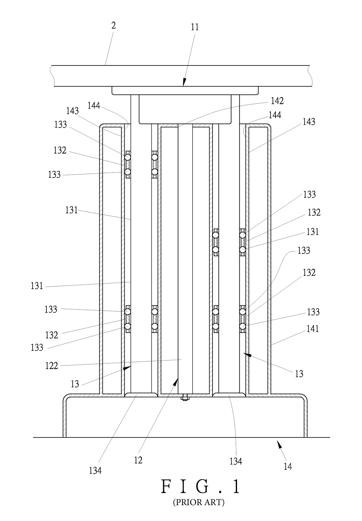
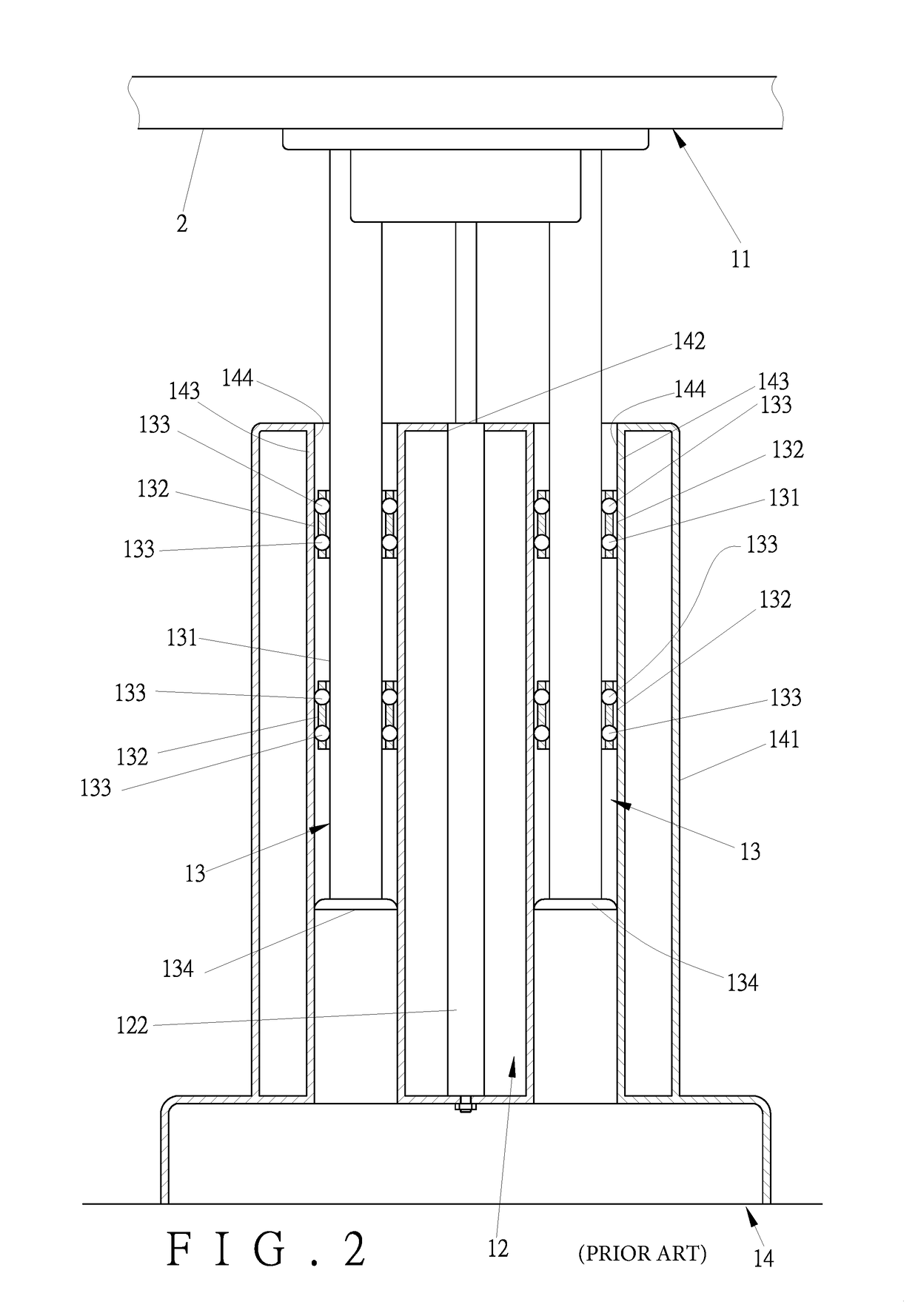
However, the function of the prior-art lifting device relies the rings 132 fitted around each of the outer peripheral surface 131 of the supporting post 13 and the balls 133 installed in the rings 132, which involve complicated and time-consuming assembling works.

Method used


Image

  • Lifting device
  • Lifting device
  • Lifting device

Examples


Embodiment Construction

[0017]The invention as well as a preferred mode of use, further objectives and advantages thereof will be best understood by reference to the following detailed description of illustrative embodiments when read in conjunction with the accompanying drawings.

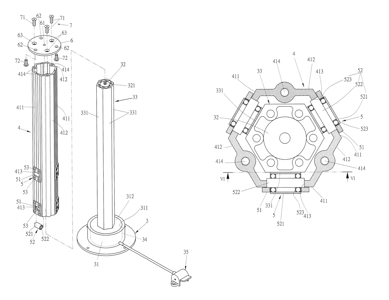
[0018]Referring to FIGS. 3 and 4, in one embodiment of the present invention, a lifting device comprises a driving unit 3, a moving tube 4, and a rolling unit 5.

[0019]The driving unit 3 includes a base 31 settled on the ground, an activating shaft 32, a sleeve 33, an activating cylinder 34, and a controlling member 35. The base 31 has a positioning socket 311 and a lid 312. The activating cylinder 34 is installed in the positioning socket 311. It is to be noted that the activating cylinder 34 in the present embodiment is illustratively a pneumatic cylinder, but not limited thereto. The lid 312 serves to close the positioning socket 311 and thereby cover the activating cylinder 34. The activating shaft 32 has its lower end passing ...


PUM


Abstract

A lifting device includes a driving unit, a moving tube, and a rolling unit. The driving unit includes an activating shaft having one end connected to an external object, a sleeve being fixed around the activating shaft and having axially extending flat surfaces, an activating cylinder connected to an opposite end of the activating shaft for driving the activating shaft to move with respect to the sleeve, and a controlling member connected to the activating cylinder for controlling the activating cylinder. The moving tube is mounted around the sleeve and connected to the external object. The movement of the activating shaft synchronously makes the moving tube move upward or downward. The rolling unit includes a plurality of rollers that are rotatably attached to the moving tube and maintain contacting the flat surfaces of the sleeve. Thereby, the lifting device lifts and lowers the external object stably.

Description

BACKGROUND OF THE INVENTION[0001]1. Technical Field[0002]The present invention relates to lifting device, and more particularly to a lifting device that is designed to lift and lower an external object stably.[0003]2. Description of Related Art[0004]A table adjustable in terms of height is convenient and welcome by various users. There are thus lifting devices designed to lift and lower a table top to a desired altitude, such as Taiwan Patent No. M461623U1, titled “Lifting Device.” Referring to FIG. 1 and FIG. 2, the prior-art lifting device includes an upper seat 11, a gas struts 12 attached to the upper seat 11 from below, two supporting posts 13 extending downward from the upper seat 11, and a lower seat 14 for receiving the gas struts 12 and the supporting posts 13. The gas struts 12 has a piston rod 121 connected to the upper seat 11, and a cylinder tube 122 mounted around the piston rod 121. The supporting posts 13 are located at two opposite sides of the gas struts 12. Each o...

Claims


Application Information

Patent Timeline
Patent Type & Authority Patents(United States)
IPC IPC(8): F16M11/00A47C3/30A47B9/20F16B7/10A47B19/06A47B9/10B66F3/00
CPCA47B9/10A47B9/20A47B19/06A47C3/30B66F3/00F16B7/10A47B2200/0052B66F3/26
Inventor LIN, YEN-CHUN
Owner LIN YEN CHUN
Learn More