Access tunnel to an aircraft

a technology for accessing aircraft tunnels and aircraft, which is applied in the field of aircraft tunnels, can solve the problems of increasing the width of the passageway over the length of the tunnel element, and the absolute limit of the number of tunnel elements connected in such a manner, so as to achieve the effect of increasing the number of passageways and reducing the width

Active Publication Date: 2017-08-29
HUBNER GMBH
View PDF16 Cites 5 Cited by
  • Summary
  • Abstract
  • Description
  • Claims
  • Application Information

AI Technical Summary

Benefits of technology

[0007]It is an objective of the invention to connect a plurality of tunnel elements to one another such that they can be stored in one another in a space-saving manner without the clearance width reducing as the number of tunnel elements increases.
[0008]According to one embodiment in accordance with the invention, a plurality of the tunnel elements are formed as tapering conically in the direction of the longitudinal axis of each tunnel element such that the tunnel elements can be pushed into one another. It becomes clear from this that all of the tunnel elements are formed the same, that is each tunnel element has the same respective clearance width at both ends, with each tunnel element, however, having a larger passage width at one end than at the oppositely disposed end. The already previously named conical design of the tunnel elements results from this. This conical design of the tunnel elements, however, has the effect that the individual tunnel elements are displaceable into one another for a space-saving storage in a similar manner to shopping carts.
[0011]To prevent water from penetrating into the interior of the access tunnel formed by the tunnel elements in the pulled-apart state of the tunnel elements and in the associated radial spacing due to the conical design of the tunnel elements, the frame of archway shape which is larger in circumference has a seal of corresponding archway shape with respect to the adjacent tunnel element. The seal of archway shape is of a flexible design to ensure the leak tightness by the seal on the pushing together of the tunnel elements or on their pulling apart. In accordance with a special feature, provision is made in this connection that the seal of archway shape is elastic at least in the roof region of the tunnel element. Elastic is understood such that the seal is designed in a similar manner to an elastic band in the roof region. Provision is advantageously furthermore made in this connection that the elastic seal of archway shape lies under strain on the cover of the adjacent tunnel element in the roof region of the tunnel element to ensure a very high degree of leak tightness with respect to penetrating moisture. The seal in the region of the limbs of the frame of archway shape is in this respect only flexible in the manner of a cloth which prevents water entering between the vertical side surfaces of two adjacent tunnel elements in driving rain.
[0012]A seal has been found to be particularly durable which has a reinforcement material coated with an elastomer at at least one side; this means that the seal of archway shape comprises, e.g. in the manner of plastic tarpaulin, a fabric coated with an elastomer. Provision is furthermore made in accordance with a special feature of the invention that the frame of archway shape which is smaller in circumference has two essentially vertically extending limbs at which a respective guidance device for persons proceeding through the access tunnel is arranged. It has already been pointed out at another passage that the tunnel elements are conical, with each tunnel element having a larger frame of archway shape at a front end than at the oppositely disposed end. This means that when the tunnel elements are pulled apart to form an access tunnel, there is a radial spacing between the inner smaller frame of archway shape and the outer larger frame of archway shape of the adjacent tunnel element. To prevent passengers in a crowd from running against the smaller frame of archway shape of the one tunnel element at the front, a respective guidance device is arranged at the essentially vertically extending limbs. Such a guidance device is advantageously designed as a wing pivotable about a vertical axis, that is the wing is arranged in a manner similar to a swing door at the frame of archway shape which is smaller in circumference. The wing is under the load of a spring which provides that the wing is urged in the direction of the frame of the adjacent tunnel element. The pivotable wing advantageously extends approximately over the length or over the height of the limb of the frame of archway shape to save the passengers using the access tunnel from colliding with the frame of archway shape.

Problems solved by technology

It is disadvantageous therein that if a plurality of such tunnel elements are telescopically connected to one another, the clearance width reduces more and more over the length of the tunnel element.
This means that the number of the tunnel elements connected in such a manner are absolutely limited.
It has furthermore been found to be disadvantageous that, due to the guiding of the individual tunnel elements into one another, a substantial force requirement is necessary to pull the individual elements apart to form the access tunnel.

Method used


Image

  • Access tunnel to an aircraft
  • Access tunnel to an aircraft
  • Access tunnel to an aircraft

Examples


Embodiment Construction

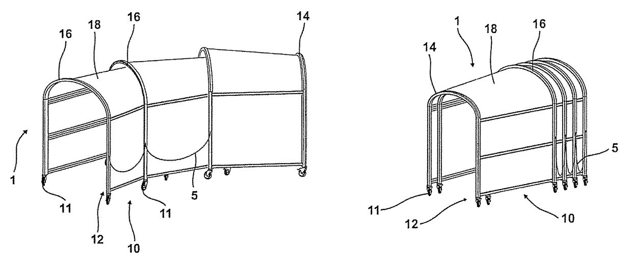
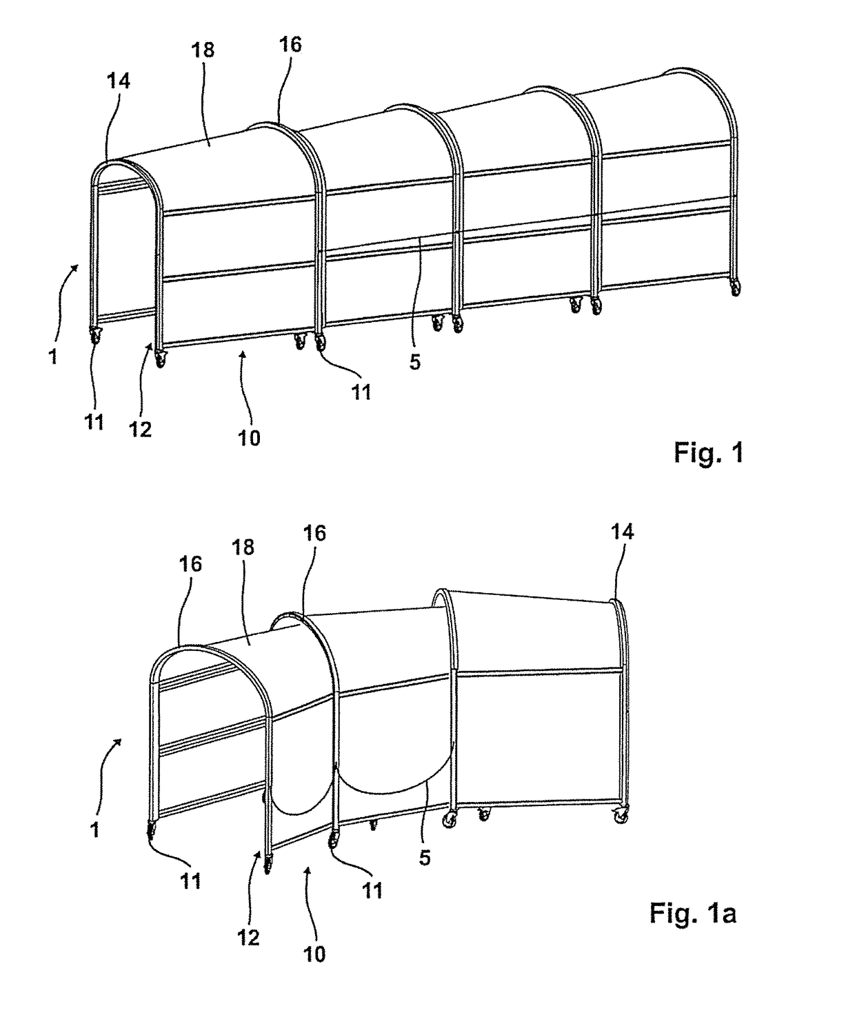
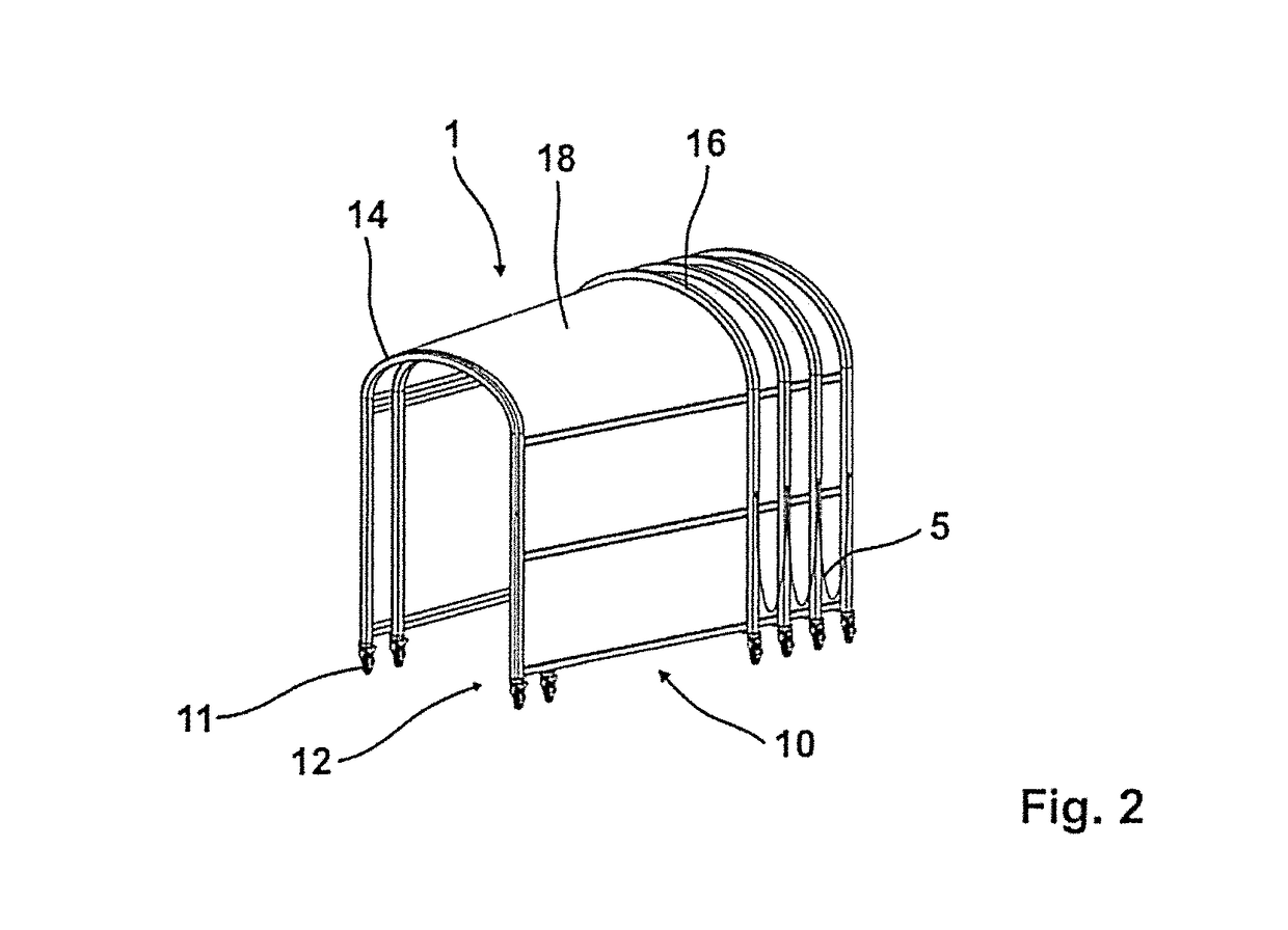
[0023]An access tunnel 1 having a total of four tunnel elements 10 results from FIG. 1. Each tunnel element 10 has a framework 12 having four rollers 11, wherein the framework 12 has a smaller frame 14 of archway shape at one end and a frame 16 of archway shape which is larger in comparison therewith at the opposite end. The term “smaller frame of archway shape” is to be understood in this respect in relation to the term “larger frame of archway shape”; that is, the smaller frame of archway shape has a smaller circumference than the frame 16 of archway shape larger in relation thereto such that a conical extent of the individual tunnel elements 10 results in the longitudinal direction, as is shown in FIG. 1. The cornering of an access tunnel 1 having a plurality of tunnel elements 10 is shown in FIG. 1a. The framework marked by 12 has a cover 18, for example composed of a transparent plastic, over its circumference.

[0024]The individual tunnel elements 10 are connected to one another...


PUM


Abstract

An access tunnel to an aircraft includes a plurality of tunnel elements each having a longitudinal axis, each tunnel element tapering conically in the direction of the longitudinal axis such that the tunnel elements can be pushed into each other.

Description

CROSS REFERENCE TO RELATED APPLICATION[0001]This application claims priority to European Application Ser. No. EP 15 173 521.4 filed Jun. 24, 2015, which is incorporated herewith in its entirety by reference thereto.FIELD OF THE INVENTION[0002]The present invention relates generally to an aircraft tunnel comprising a plurality of tunnel elements which are displaceably connected to each other.BACKGROUND OF THE INVENTION[0003]An access tunnel to an aircraft, for example from a parked bus or from a part of a building, is sufficiently known from the prior art. Such access tunnels are used when access to the aircraft should be made possible for passengers from an exit of a building at ground level to the taxiway area without them being exposed to weather conditions. Such access tunnels are known, as already stated.[0004]For example, PCT / DE2013 / 000513 discloses an access tunnel which has a plurality of tunnel elements, whereby the access tunnel can be adapted to the required length. It is ...

Claims


Application Information

Patent Timeline
Patent Type & Authority Patents(United States)
IPC IPC(8): B64F1/30B64F1/305E04H15/36
CPCB64F1/30B64F1/305E04H15/36
Inventor GUTKUHN, DETLEFMANDER, KAISCHARF, LOTHARBENKHOFF, HERMANNHUBNER, REINHARD
Owner HUBNER GMBH
Why Eureka
Try Eureka