
Corner flashing insert for recessed windows

a corner flashing and recessed window technology, applied in the field of construction, can solve the problems of still requires time-consuming and error-prone applications in the field when installing the flashing, and requires time-consuming and error-prone problems in the field, so as to achieve the effect of improving handling and facilitating placemen

Active Publication Date: 2017-08-29
TOP IND INC
View PDF22 Cites 7 Cited by
  • Summary
  • Abstract
  • Description
  • Claims
  • Application Information

AI Technical Summary

Benefits of technology

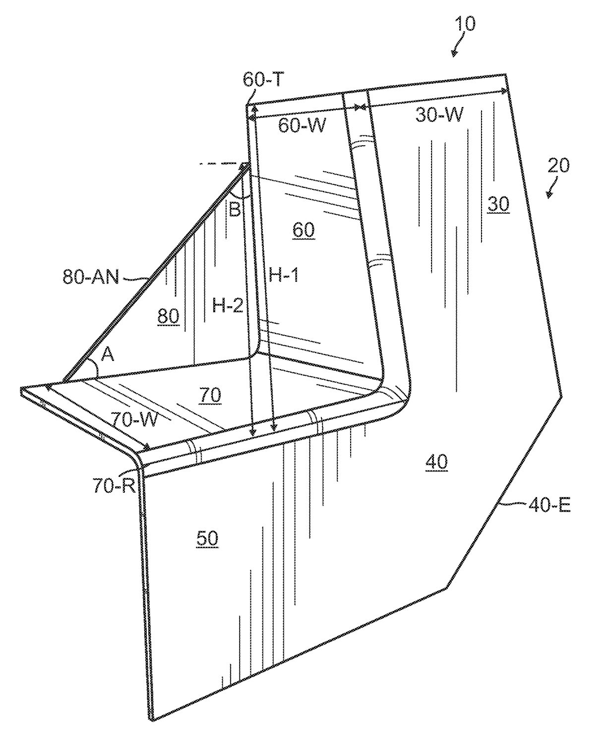
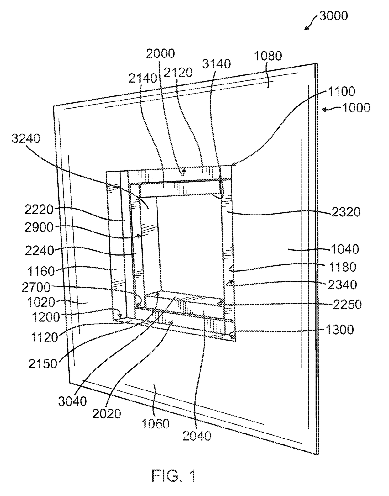
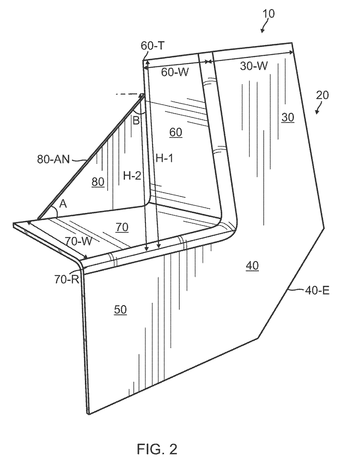
The present invention provides a flashing apparatus designed to protect the lower corners of a structure from water intrusion. It is uniquely shaped to fit the depth of recessed window frames and provides three legs of protection: the outside wall, the corner recessed legs, and the recessed back leg. The recessed back leg is optimally integrated with a sill pan end dam placed in an adjacent corner of the recessed window frame without requiring any field modification. Additionally, the flashing insert has a combined object of providing protection for both inside and outside recessed corner framing configurations from water intrusion.

Problems solved by technology

This creates time-consuming and error plagued problems.
While an improvement over the claim 1 subgroup, it still requires time-consuming application in the field when installing this flashing.
This requires time-consuming and error prone problems in the field.Claim 4 depends from claim 3.

Method used


Image

  • Corner flashing insert for recessed windows
  • Corner flashing insert for recessed windows
  • Corner flashing insert for recessed windows

Examples


Embodiment Construction

[0071]Although specific embodiments of the present invention will now be described with reference to the drawings, it should be understood that such embodiments are by way of example only and merely illustrative of but a small number of the many possible specific embodiments which can represent applications of the principles of the present invention. Various changes and modifications obvious to one skilled in the art to which the present invention pertains are deemed to be within the spirit, scope and contemplation of the present invention as further defined in the appended claims.

PARTS LIST

[0072]corner flashing insert . . . 10[0073]outside wall leg . . . 20[0074]rear surface of outside leg . . . 20-R[0075]outside wall leg in a vertical plane . . . 30[0076]rear surface of outside wall leg in a vertical plane . . . 30-R[0077]width of outside wall leg in a vertical plane . . . 30-W[0078]top of outside wall leg in a vertical plane . . . 30-T[0079]outside wall leg angle . . . 40[0080]ou...


PUM


Abstract

A corner flashing insert including a one-piece, pre-formed flashing with an outside wall, a recessed jamb leg in the vertical plane and a recessed sill leg in the horizontal plane, the recessed sill leg in the horizontal plane having a rear surface, the recessed jamb leg in the vertical plane having a first vertical height with a first distance from a top of the jamb leg in the vertical plane to the rear surface of the recessed sill leg in the horizontal plane. The corner flashing insert also includes a recessed back leg in the vertical plane having a second vertical height with a second distance from where the recessed back leg in the vertical plane joins the recessed jamb leg in the vertical plane to the rear surface of the recessed sill leg in the horizontal plane. The first vertical height is greater than the second vertical height.

Description

BACKGROUND OF THE INVENTION[0001]1. Field of the Invention[0002]The present invention relates in general to the field of construction of both residential and commercial structures. More specifically, the present invention relates to the field of recessed windows and problems associated with water from elements such as rain collecting in corners of areas between an exterior wall of a structure and the frame of the recessed window. The present invention further relates to the field of flashing to protect such corners from collecting water.[0003]2. Description of the Prior Art[0004]The construction situation addressed in this patent is as follows. In recessed window construction, an outer wall opening is flush with the exterior wall of the structure. A recessed window frame (into which a window is installed) lies in a plane behind the exterior wall and has a smaller height and width. Lower corners between the exterior wall and the recessed window frame can accumulate water from element...

Claims


Application Information

Patent Timeline
IPC IPC(8): E06B1/62E06B1/34E06B7/26E06B3/30E06B1/70E04B1/68
CPCE06B1/62E04B1/6803E06B1/34E06B1/702E06B3/308E06B7/26E06B2001/628E04B1/665
Inventor ROHOVIT, JOHNSTROUP, JOHN
Owner TOP IND INC
Learn More