Organic electroluminescent element

a technology of electroluminescent elements and organic electroluminescent elements, which is applied in the direction of phosphorescent light-emitting units, solid-state devices, chemistry apparatus and processes, etc., can solve the problems of low luminous efficiency, reduced total luminous efficiency, and low luminous efficiency of organic electroluminescent elements

Active Publication Date: 2017-08-29
SAMSUNG DISPLAY CO LTD
View PDF32 Cites 30 Cited by
  • Summary
  • Abstract
  • Description
  • Claims
  • Application Information

AI Technical Summary

Benefits of technology

[0011]The present invention can realize high luminous efficiency of the organic electroluminescent element.

Problems solved by technology

With this method, although the desired chromaticity can be easily realized, the total luminous efficiency tends to decrease because the fluorescent light-emitting units whose luminous efficiency is lower than that of the phosphorescent light-emitting unit are stacked.
However, in consideration of lighting use, the former is a double layer structure of fluorescent light-emitting units, and is lower in the luminous efficiency than a structure including phosphorescent light-emitting units.
Therefore, compared with a red monochromatic light-emitting unit, the driving voltage is relatively high, and as a result the luminous efficiency becomes low.
However, the aforementioned (1) is the lowest in the luminous efficiency.
The aforementioned (3) requires a blue phosphorescent material and therefore it may leave a big problem on a lifetime.

Method used


Image

  • Organic electroluminescent element
  • Organic electroluminescent element
  • Organic electroluminescent element

Examples


first embodiment

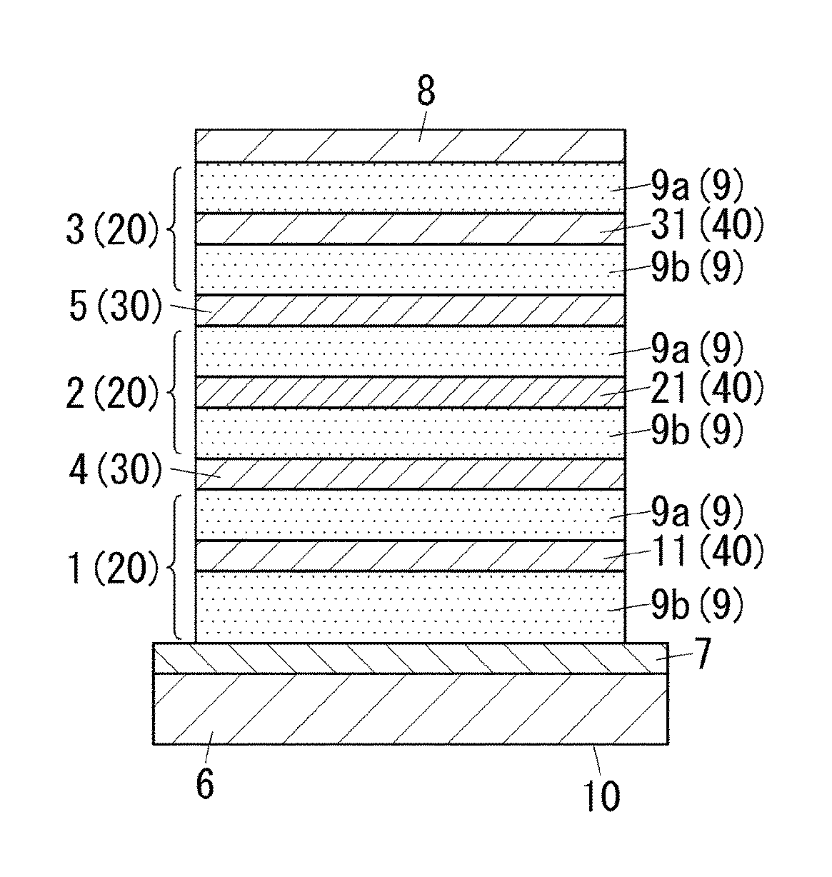
[0019]FIG. 1 shows an example of an organic EL element 10 of the first embodiment. The organic EL element 10 has a multi-unit structure including multiple light-emitting units 20. The multi-unit structure is a structure in which multiple light-emitting units 20 stacked in thickness direction are arranged so as to be connected electrically in series between an anode and a cathode. The organic EL element 10 has a triple-unit structure that includes a first light-emitting unit 1, a second light-emitting unit 2, and a third light-emitting unit 3 as the light-emitting units 20. The organic EL element 10 may include two or more further light-emitting units in addition to the first light-emitting unit 1, the second light-emitting unit 2, and the third light-emitting unit 3.

[0020]The organic EL element 10 further includes interlayers 30, a substrate 6, a first electrode 7, and a second electrode 8. Each interlayer 30 is interposed between adjacent light-emitting units 20. A first interlayer...

second embodiment

[0059]FIG. 5 shows an example of an organic EL element 101 of the second embodiment. This organic EL element 101 is different from the first embodiment in a structure of a second light-emitting unit 2. The second embodiment and the first embodiment are the same in components other than the second light-emitting unit 2. The same components as the first embodiment shown in FIG. 1 are attached with the same reference signs, and therefore descriptions thereof will be omitted from the following explanation made to the second embodiment.

[0060]The second light-emitting unit 2 mentioned above is formed to contain a red light-emitting material. This red light-emitting material is provided in a form of a layer which is on a surface, close to the first electrode 7, of the yellow light-emitting layer 21 and defines a red auxiliary light-emitting layer 22. This red auxiliary light-emitting layer 22 can contribute to minor adjustment of an emission color of the organic EL element 101.

[0061]As a r...

third embodiment

[0063]FIG. 6 shows an example of an organic EL element 102 of the third embodiment. This organic EL element 102 is different from the first embodiment in a structure of the third light-emitting unit 3. The first embodiment and the third embodiment are the same in components other than the third light-emitting unit 3. The same components as the first embodiment shown in FIG. 1 are attached with the same reference signs, and therefore descriptions thereof will be omitted from the following explanation made to the third embodiment.

[0064]The third light-emitting unit 3 mentioned above is formed to contain a red light-emitting material. This red light-emitting material is provided in a form of a layer which is on a surface, close to the first electrode 7, of the blue light-emitting layer 31 and defines a red auxiliary light-emitting layer 32. This red auxiliary light-emitting layer 32 can contribute to minor adjustment of an emission color of the organic EL element 102.

[0065]As a result ...


PUM

PropertyMeasurementUnit
peak emission wavelengthaaaaaaaaaa
thicknessaaaaaaaaaa

Abstract

The objective is to provide an organic electroluminescent element with an improved luminous efficiency. The organic electroluminescent element has a structure in which a first light-emitting unit containing a phosphorescent red light-emitting material, a second light-emitting unit containing a phosphorescent yellow light-emitting material, and a third light-emitting unit containing a fluorescent blue light-emitting material are stacked with interlayers in-between. A peak emission wavelength of the phosphorescent yellow light-emitting material is in a range of 530 nm to 570 nm. A peak emission wavelength of the fluorescent blue light-emitting material is in a range of 440 nm to 480 nm. The organic electroluminescent element has a ratio of a yellow emission intensity to a blue emission intensity in a range of 1.0 to 2.0. The organic electroluminescent element further has a ratio of a red emission intensity to the blue emission intensity in a range of 1.5 to 3.0.

Description

TECHNICAL FIELD[0001]The present invention relates to organic electroluminescent elements, and more specifically to an organic electroluminescent element (hereinafter referred to as “organic EL element” if needed) suitable for use in lighting devices and others.BACKGROUND ART[0002]In the past, there has been known an organic EL element which includes a stack in which an organic light-emitting layer is between a pair of electrodes. In this organic EL element, the organic light-emitting layer produces light when electrons and holes are recombined inside the organic light-emitting layer. Further, there has been known another organic EL element having a multi-unit structure which includes multiple light-emitting units (for example, see Patent Literature 1 to 3).[0003]Patent literature 1 relates to an organic EL element in which multiple light-emitting units are connected in series, and discloses a method for obtaining light with desired chromaticity by mixing light from the multiple lig...

Claims


Application Information

Patent Timeline
Patent Type & Authority Patents(United States)
IPC IPC(8): H01L27/32H01L51/50C09K11/06H01L51/00
CPCH01L27/3209C09K11/06H01L51/5016H01L51/5044C09K2211/10C09K2211/1011C09K2211/1029C09K2211/1088C09K2211/185H01L51/005H01L51/006H01L51/0058H01L51/0085H10K50/131H10K59/32H10K50/11H10K85/60H10K85/342H10K85/626H10K85/633H10K2101/10
Inventor TSUJI, HIROYAYAMAE, KAZUYUKIOHARA, SATOSHIKITTICHUNGCHIT, VARUTT
Owner SAMSUNG DISPLAY CO LTD
Why Eureka
Try Eureka