Check patentability & draft patents in minutes with Patsnap Eureka AI!

Power conversion apparatus

a power conversion device and power conversion technology, applied in the direction of solid-state devices, basic electric elements, semiconductor devices, etc., can solve the problems of difficult to maintain at suitable temperature the surfaces of the conversion device and the heat-producing source dispersed in the interior of the casing, and achieve the effect of reducing weight and size and effectively cooling the power conversion uni

Active Publication Date: 2017-09-05
HONDA MOTOR CO LTD
View PDF42 Cites 0 Cited by
  • Summary
  • Abstract
  • Description
  • Claims
  • Application Information

AI Technical Summary

Benefits of technology

[0007]In view of the foregoing prior art problems, it is an object of the present invention to provide an improved power conversion apparatus which can be reduced in weight and size and yet can effectively cool the power conversion units and the cool heat-producing sources disposed dispersedly in the interior of the casing.
[0009]According to the present invention, the cooling air passage is defined with the plurality of power conversion units disposed in such a manner that the respective heat radiation sections of the power conversion units are opposed to each other, and the first cooling fan supplies cooling air from upstream of the cooling air passage directly to the cooling air passage. With such arrangements, the cooling air blown out from the first cooling fan can be applied directly to the heat radiation sections of the plurality of power conversion units, so that the heat radiation sections can be cooled efficiently.
[0010]Further, according to the present invention, the cooling air can be supplied by the first cooling fan directly to the cooling air passage, the single or same cooling air passage can be used for the heat radiation sections of the plurality of power conversion units. In other words, the same first cooling fan can be used for the plurality of power conversion units. Therefore, it is not necessary to provide separate cooling air passages and first cooling fans for the heat radiation sections of the plurality of power conversion units. Thus, it is possible to not only reduce the numbers of the cooling air passages and first cooling fans, but also reduce a size of a space required for providing therein such cooling air passages and cooling fans. As a result, the plurality of power conversion units and the cooling air passage can be provided efficiently in a compact space, and thus, a reduced weight and size of the portable power conversion apparatus is achievable.
[0011]Further, according to the present invention, the second cooling fan is disposed downstream of the cooling air passage at a position spaced (or offset) from the power conversion units defining the cooling air passage. Namely, the second cooling fan is disposed in such a manner that an air-sucking opening of the second cooling fan faces the interior of the casing over a wide area or range. Thus, by driving the second cooling fan, it is possible to discharge air within the entire region (wide range) of the casing to the outside of the casing. By the air within the casing being discharged as above, heat radiated from the surfaces of the power conversion units and heat radiated from various heat-producing sources provided dispersedly within the casing can be effectively discharged to the outside of the casing together with the air within the casing. In this way it is possible to effectively cool the conversion units and the heat-producing sources provided dispersedly within the casing. Note that the power conversion units may be in the form of semiconductor devices or other devices.
[0012]In a preferred implementation of the present invention, the first cooling fan is an axial flow fan provided on an extension line of the cooling air passage. Thus, cooling air can be supplied from the first cooling fan directly and straight to the cooling air passage. In this way, a large amount of cooling air can be supplied from the first cooling fan to the cooling air passage, and thus, the opposed heat radiation sections can be cooled with a high efficiency by the cooling air.

Problems solved by technology

Thus, temperature in the interior of the casing may undesirably increase due to the heat radiated directly from the surfaces of the conversion devices to the interior space of the casing and the heat radiated from the heat-producing sources to the interior space of the casing.
However, with the power conversion apparatus disclosed in the above-identified U.S. Pat. No. 5,355,822, where the cooling air is supplied to between the opposed cooling fans, it is difficult to cool the entire interior space of the casing, and thus, it is difficult to maintain at suitable temperature the surfaces of the conversion devices and the heat-producing sources disposed dispersedly in the interior of the casing.
However, such an approach would further increase the necessity for maintaining at suitable temperature the surfaces of the conversion devices (power conversion units) and the heat-producing sources disposed dispersedly in the interior of the casing

Method used


Image

  • Power conversion apparatus
  • Power conversion apparatus
  • Power conversion apparatus

Examples


Embodiment Construction

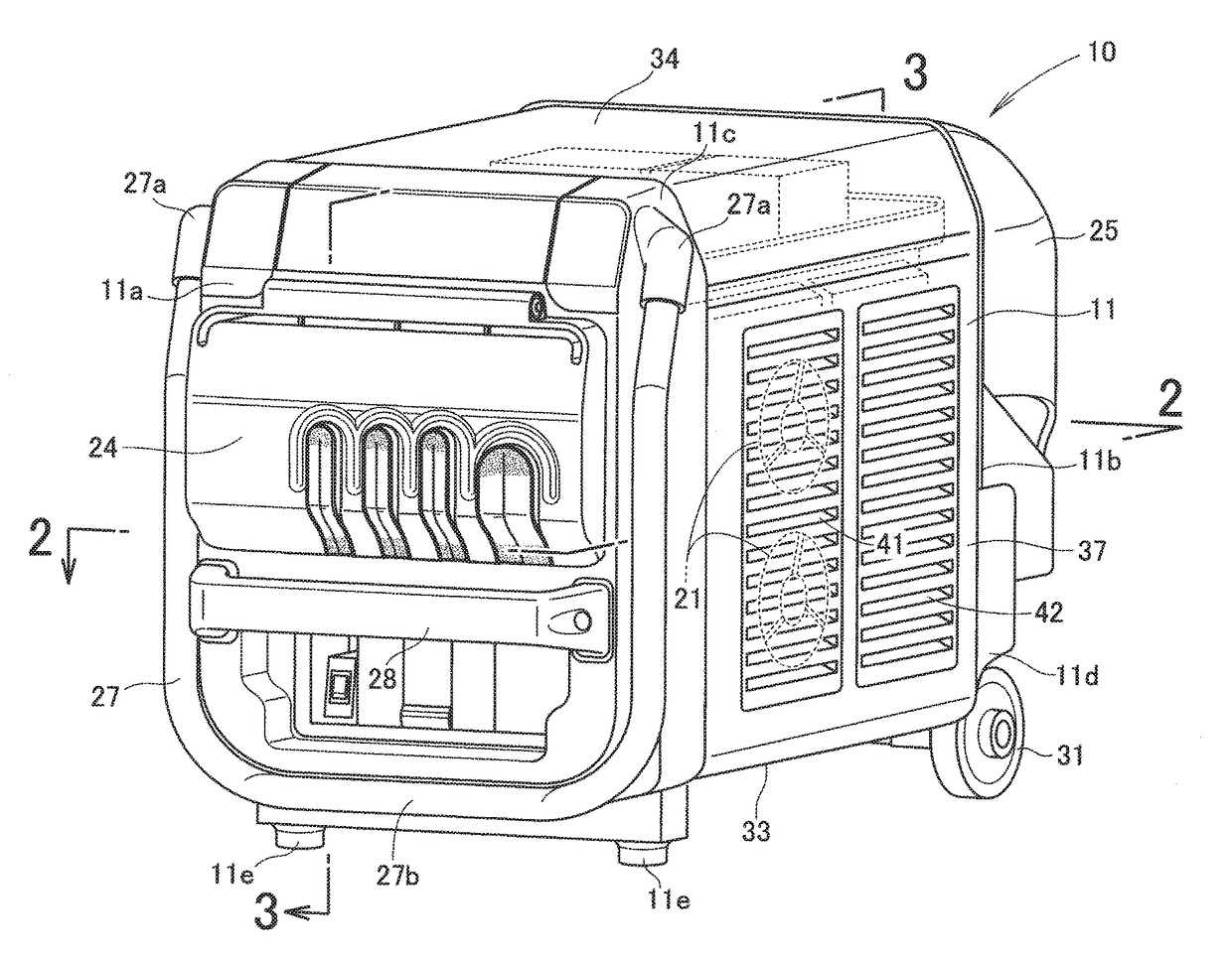
[0023]In the following description, the terms “front”, “rear”, “left” and “right”, etc. are used to refer to directions as viewed from a human operator towing a power conversion apparatus 10.

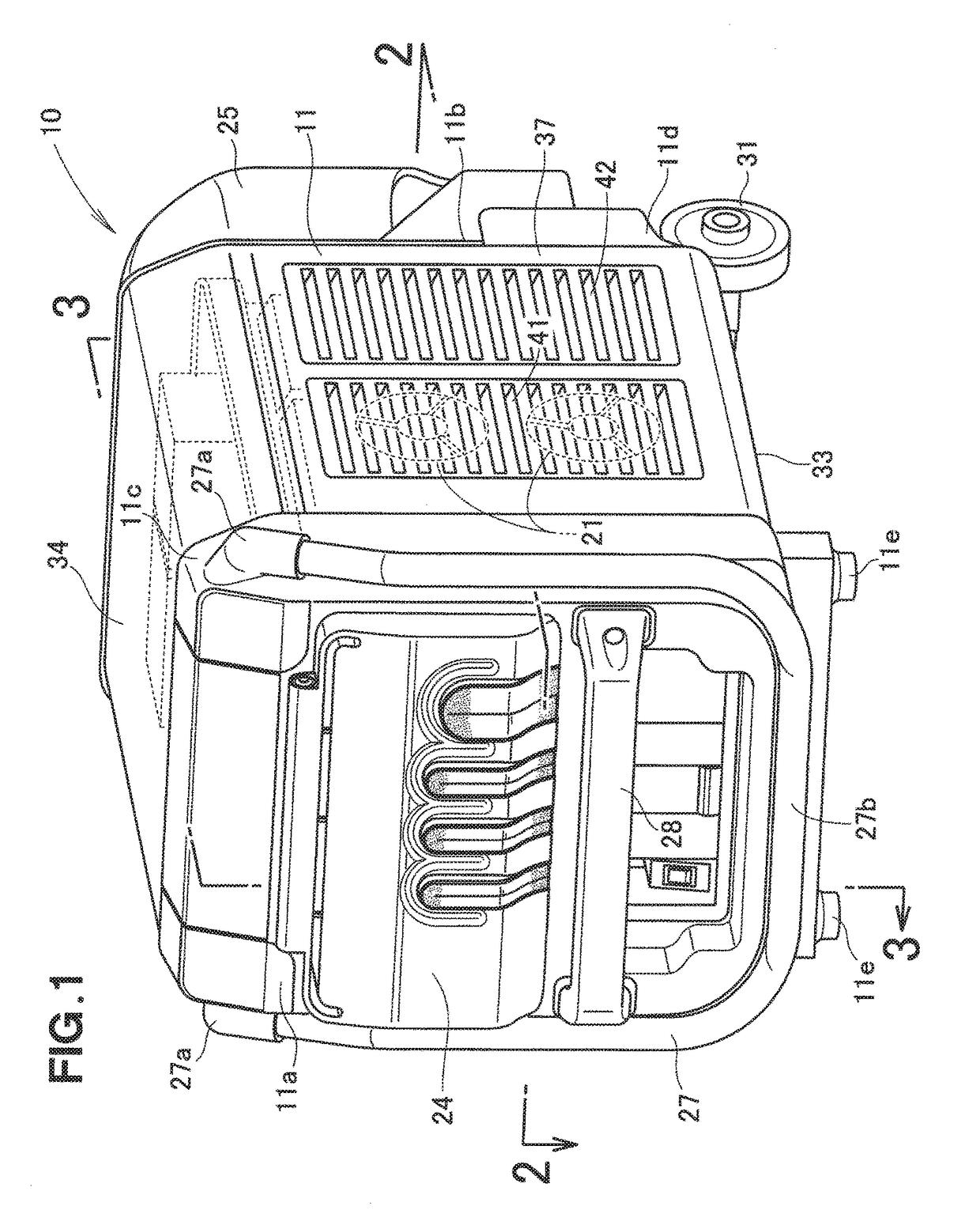
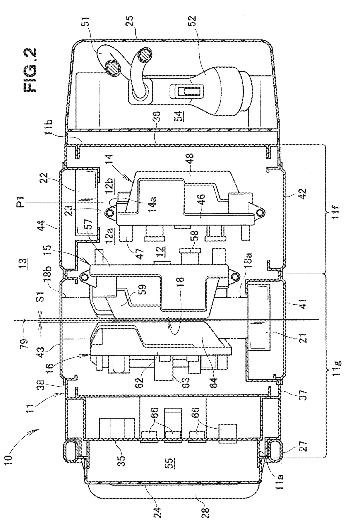
[0024]FIG. 1 is a perspective view showing an embodiment of a power conversion apparatus 10 of the present invention, and FIG. 2 is a sectional view taken along the 2-2 line of FIG. 1. As shown in FIGS. 1 and 2, the power conversion apparatus 10 includes: an apparatus casing 11 of a substantial rectangular parallelepiped shape; a plurality of power conversion units 14 to 16 provided in the interior 12 of the casing 11; a cooling air passage 18 formed or defined between the plurality of power conversion units 14 to 16; a plurality of blowing fans (first cooling fans) 21 for supplying external air to the cooling air passage 18; and a plurality of sucking fans (second cooling fans) 22 for discharging internal air from the interior 12 of the casing 11 to the outside 13.

[0025]The power conversion app...


PUM


Abstract

A power conversion apparatus includes: a cooling air passage defined with cooling fins of upper and lower converters and cooling fins of an inverter opposed to each other; upper and lower blowing fans provided upstream of the cooling air passage; and upper and lower sucking fans provided downstream of the cooling air passage and at positions offset from the converters. The blowing fans are provided for supplying cooling air from upstream of the cooling air passage, and the sucking fans are provided for discharging air from within a casing of the apparatus to the outside.

Description

FIELD OF THE INVENTION[0001]The present invention relates to power conversion apparatus which are constructed to convert DC electric power into AC electric power by means of power conversion units and supply the converted AC electric power to outside of the apparatus.BACKGROUND OF THE INVENTION[0002]Among the conventionally-known power conversion apparatus are ones in which a plurality of cooling units (hereinafter referred to as “power conversion units”) are accommodated within an apparatus casing with respective cooling fins of the plurality of cooling units disposed opposed to one another, and in which cooling air is supplied to between the opposed cooling fins. In such power conversion apparatus, semiconductor devices (hereinafter referred to as “conversion devices”) are mounted on respective mounting surfaces of the power conversion units, and heat of the conversion devices is transmitted to the cooling fins.[0003]Heat of the conversion devices transmitted to the cooling fins c...

Claims


Application Information

Patent Timeline
Patent Type & Authority Patents(United States)
IPC IPC(8): H05K7/20H01L23/473H02M7/00
CPCH05K7/20909H02M7/003
Inventor SHIN, MASANORIKOMATSU, TAKAYUKINAKAGAWA, KATSUHIROYAMAMOTO, YASUNORI
Owner HONDA MOTOR CO LTD
Features
  • R&D
  • Intellectual Property
  • Life Sciences
  • Materials
  • Tech Scout
  • Unparalleled Data Quality
  • Higher Quality Content
  • 60% Fewer Hallucinations
Learn More