Check patentability & draft patents in minutes with Patsnap Eureka AI!

Positioning device, lithographic apparatus using same, and device manufacturing method

a technology of lithographic apparatus and positioning device, which is applied in the direction of dynamo-electric converter control, printers, program control, etc., can solve the problems of restricting the layout of the units reducing the efficiency of the exposure apparatus, and reducing the weight and size of the conventional dynamic brake. , to achieve the effect of improving the acceleration and speed, reducing the weight and size, and increasing the productivity of the exposure apparatus

Inactive Publication Date: 2013-08-06
CANON KK
View PDF5 Cites 0 Cited by
  • Summary
  • Abstract
  • Description
  • Claims
  • Application Information

AI Technical Summary

Benefits of technology

This solution provides a robust braking mechanism that relieves impact during emergency stops, enables increased table acceleration and speed, and contributes to improved productivity by reducing the table's weight and size without the need for a brake mechanism.

Problems solved by technology

Hence, in recent positioning devices for which the acceleration and maximum speed have been increased to attain an increase in productivity, a conventional dynamic brake provides an insufficient braking force.
Thus, problems arise in that the table 101 itself may be destroyed due to an impact caused when the table 101 collides with the shock absorber 114.
Furthermore, the shock absorber 114 requires a large stroke, i.e., a large external dimension in order to absorb a violent impact as described above, which restricts the layout of the units of the exposure apparatus.
Moreover, as with the device disclosed in Japanese Patent Laid-Open No. 1-259405, a table provided with a brake mechanism increases the weight and the size thereof, whereby it becomes difficult to increase the acceleration and the maximum speed of the table.

Method used


Image

  • Positioning device, lithographic apparatus using same, and device manufacturing method
  • Positioning device, lithographic apparatus using same, and device manufacturing method
  • Positioning device, lithographic apparatus using same, and device manufacturing method

Examples


first embodiment

(First Embodiment)

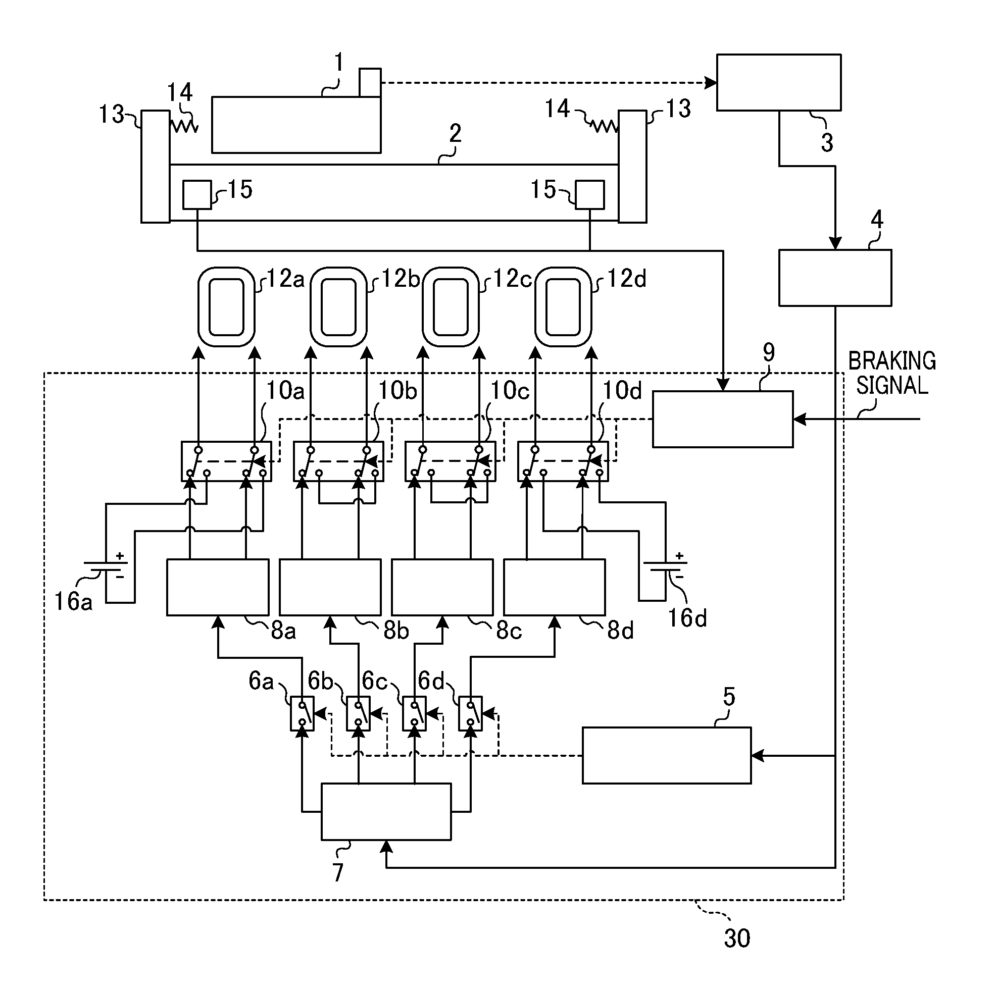
[0023]FIG. 1 is a schematic view illustrating the configuration of a positioning device according to a first embodiment of the present invention. The present embodiment illustrates the use of a linear motor serving as the motor for driving a table. The table 1 places various originals such as a reticle or various substrates such as a wafer for performing linear driving. The table 1 is mounted on a base 2, and the base 2 includes a guide (not shown) for guiding the table 1 in a predetermined axial direction. The distance over which the table 1 is moved on the guide is output by a position sensor 3 as a pulse signal. For the position sensor 3, a laser interferometer, a linear encoder, or the like may be used. The pulse signal output from the position sensor 3 is integrated by a counter 4 so as to output the table 1's current position signal.

[0024]A control unit 30 that controls a linear motor includes controllers 5, 7, and 9, electric current amplifiers 8a to 8d, ele...

second embodiment

(Second Embodiment)

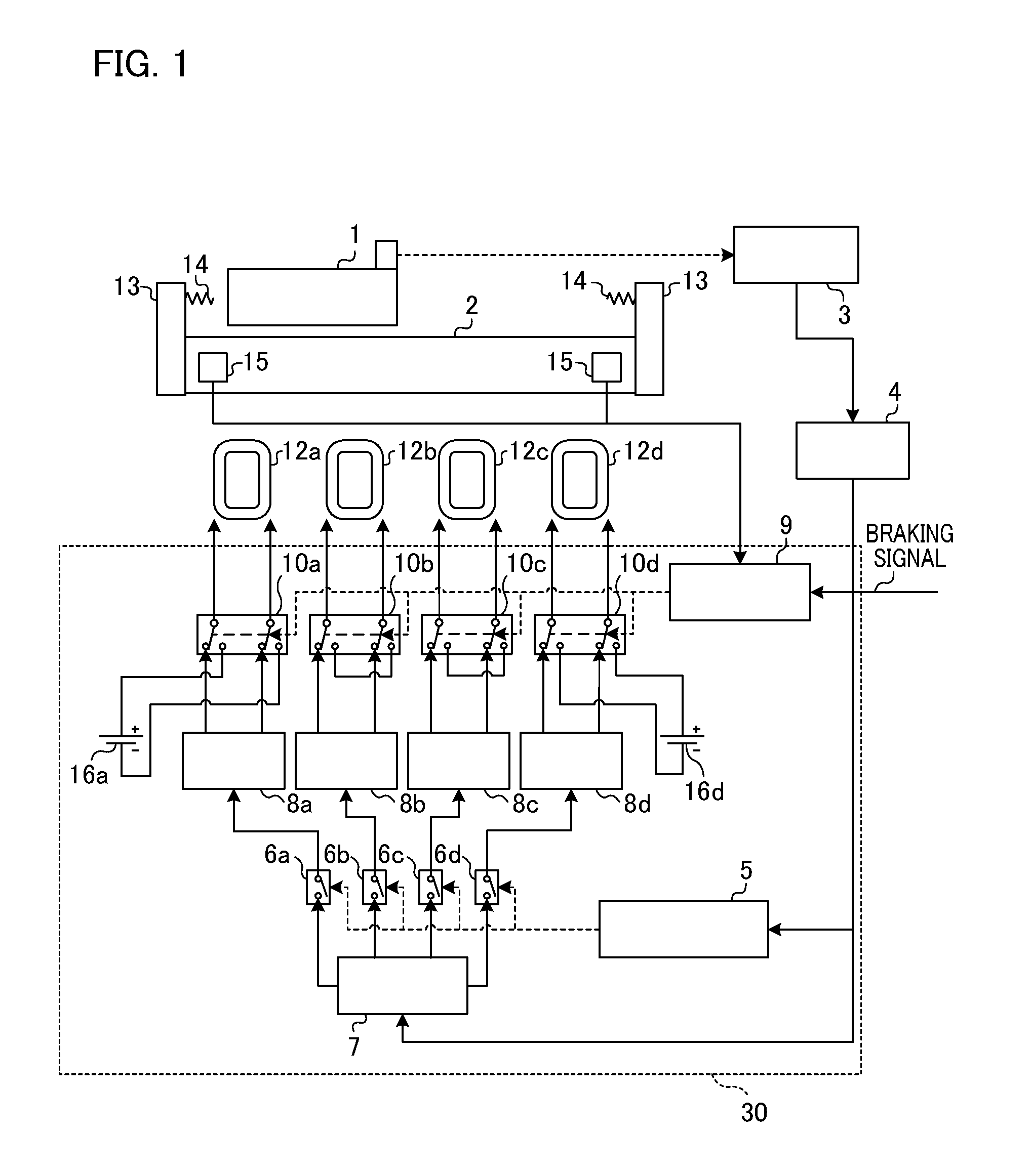
[0033]Next, a positioning device according to a second embodiment of the present invention will now be described with reference to FIG. 2. For the positioning device of the present embodiment, the electric current amplifiers 8a and 8d for performing the driving of a linear motor are employed as electric current sources during braking. The same elements as those shown in FIG. 1 and having the same function are designated by the same reference numerals and the explanation thereof will be omitted. Hereinafter, the parts shown in FIG. 2, which are different from those shown in FIG. 1, will be described in detail.

[0034]A control unit 31 that controls a linear motor includes controllers 5, 7, and 9, electric current amplifiers 8a to 8d, electric current command value setters 22a and 22d, and switches 6a to 6d, 10a to 10d, 21a and 22d. While in FIG. 1 the electric current sources 16a and 16d dedicated for braking are respectively connected to the coils 12a and 12d as the...

third embodiment

(Third Embodiment)

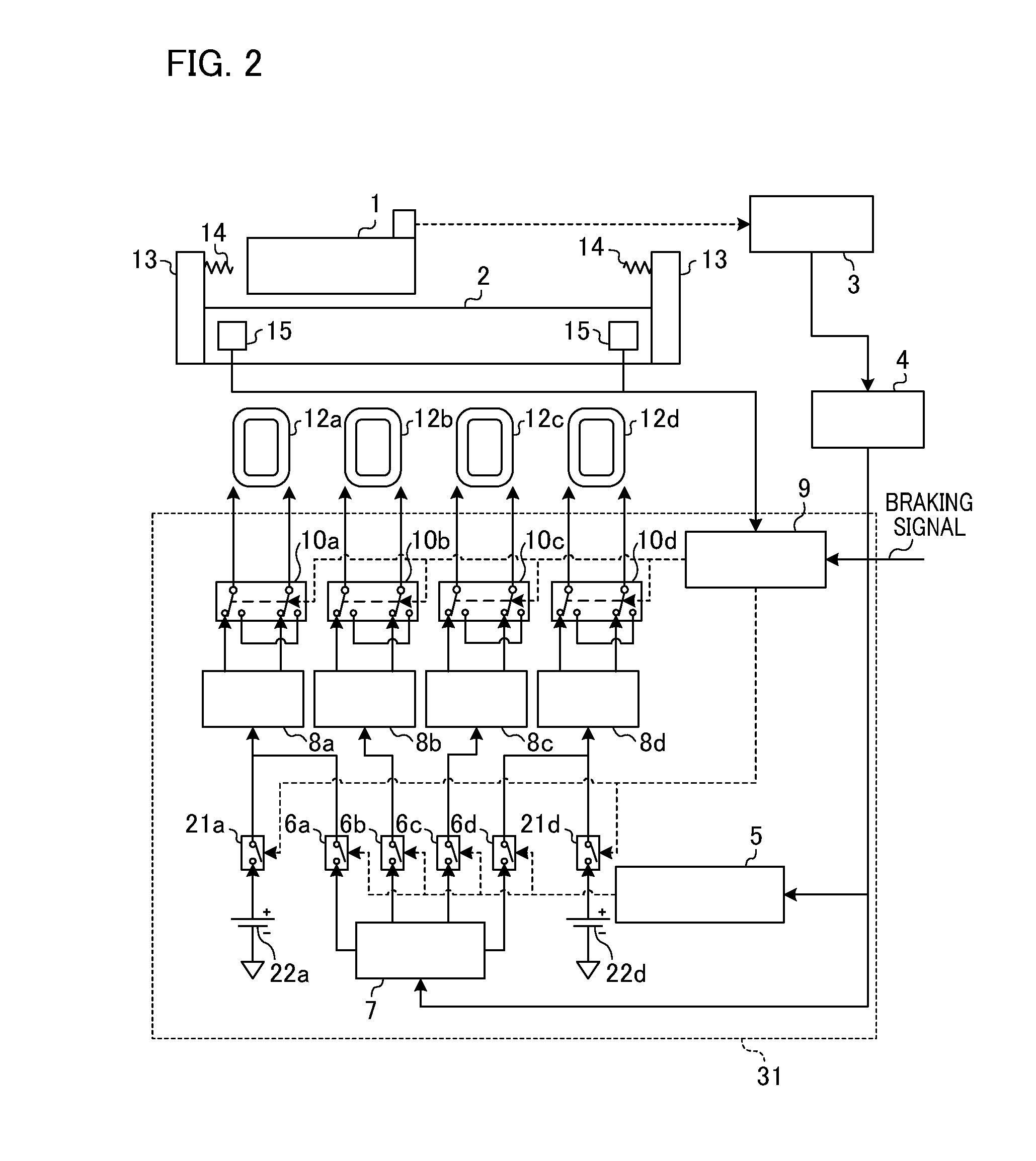
[0036]Next, a positioning device according to a third embodiment of the present invention will now be described with reference to FIG. 3. The function of the electric current command value connecting switches 21a and 21d as well as the electric current command value setters 22a and 22d described in FIG. 2 can be also realized by using the control software of the servo controller 7 as shown in FIG. 3. The positioning device of the present embodiment is configured such that a braking signal from an upper-level controller (not shown) and a detection signal from the limit detection sensor 15 are input to the servo controller 7. During normal operation, the servo controller 7 calculates the difference between the target position from an upper-level controller (not shown) and the table 1's current position from the counter 4 so as to perform control calculation such as position control or speed control, and the electric current command value calculated thereby is then ou...


PUM

PropertyMeasurementUnit
output voltageaaaaaaaaaa
areaaaaaaaaaaa
electric currentaaaaaaaaaa

Abstract

The present invention provides a positioning device for positioning a table, including a base, a motor that drives the table in the driving area on the base, a position sensor that detects the position of the table, and a control unit that controls the motor. The control unit includes a first output unit that outputs electric current for controlling the position of the table based on the output of the position sensor; a second output unit that outputs electric current for imparting a thrust force, which is directed toward the center of the driving area, to the table; and a switch unit that switches from a state in which the motor is controlled depending on the output of the first output unit to a state in which the motor is controlled depending on the output of the second output unit, based on a stopping signal for stopping the table.

Description

BACKGROUND OF THE INVENTION[0001]1. Field of the Invention[0002]The present invention relates to a positioning device for positioning a table. The present invention also relates to a lithographic apparatus using the positioning device, and a device manufacturing method.[0003]2. Description of the Related Art[0004]FIG. 7 is a schematic diagram showing the configuration of a positioning device employed in a conventional lithographic apparatus. The following positioning device is based on the assumption that a linear motor is used as the driving unit for driving a table. A table 101 places various originals such as a reticle or various substrates such as a wafer for performing linear driving. The table 101 is mounted on a base 102, and the base 102 includes a guide (not shown) for guiding the table 101 in a predetermined axial direction. The distance over which the table 101 is moved on the guide is output by a position sensor 103 as a pulse signal. The pulse signal output from the pos...

Claims


Application Information

Patent Timeline
Patent Type & Authority Patents(United States)
IPC IPC(8): G03B27/58G03B27/42H02K41/02G03F7/20
CPCG03F7/70725G03F7/70758G05B2219/42173G05B2219/36585
Inventor MAKITA, YOSHINORI
Owner CANON KK
Features
  • R&D
  • Intellectual Property
  • Life Sciences
  • Materials
  • Tech Scout
  • Unparalleled Data Quality
  • Higher Quality Content
  • 60% Fewer Hallucinations
Learn More