
Highly sensitive standoff gas sensing using carbon nanotubes and integrated wireless devices

a carbon nanotube and high-sensitivity technology, applied in the field of gas sensors, can solve the problems of false alarms, changes of the same magnitude, insufficient sensitivity for many applications, etc., and achieve the effect of low-cost wireless sensing and easy measurement of the shift of the resonant frequency

Active Publication Date: 2017-09-12
GEORGIA TECH RES CORP
View PDF1 Cites 6 Cited by
  • Summary
  • Abstract
  • Description
  • Claims
  • Application Information

AI Technical Summary

Benefits of technology

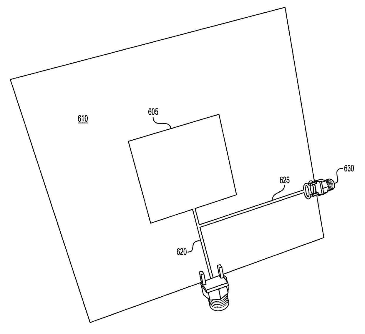
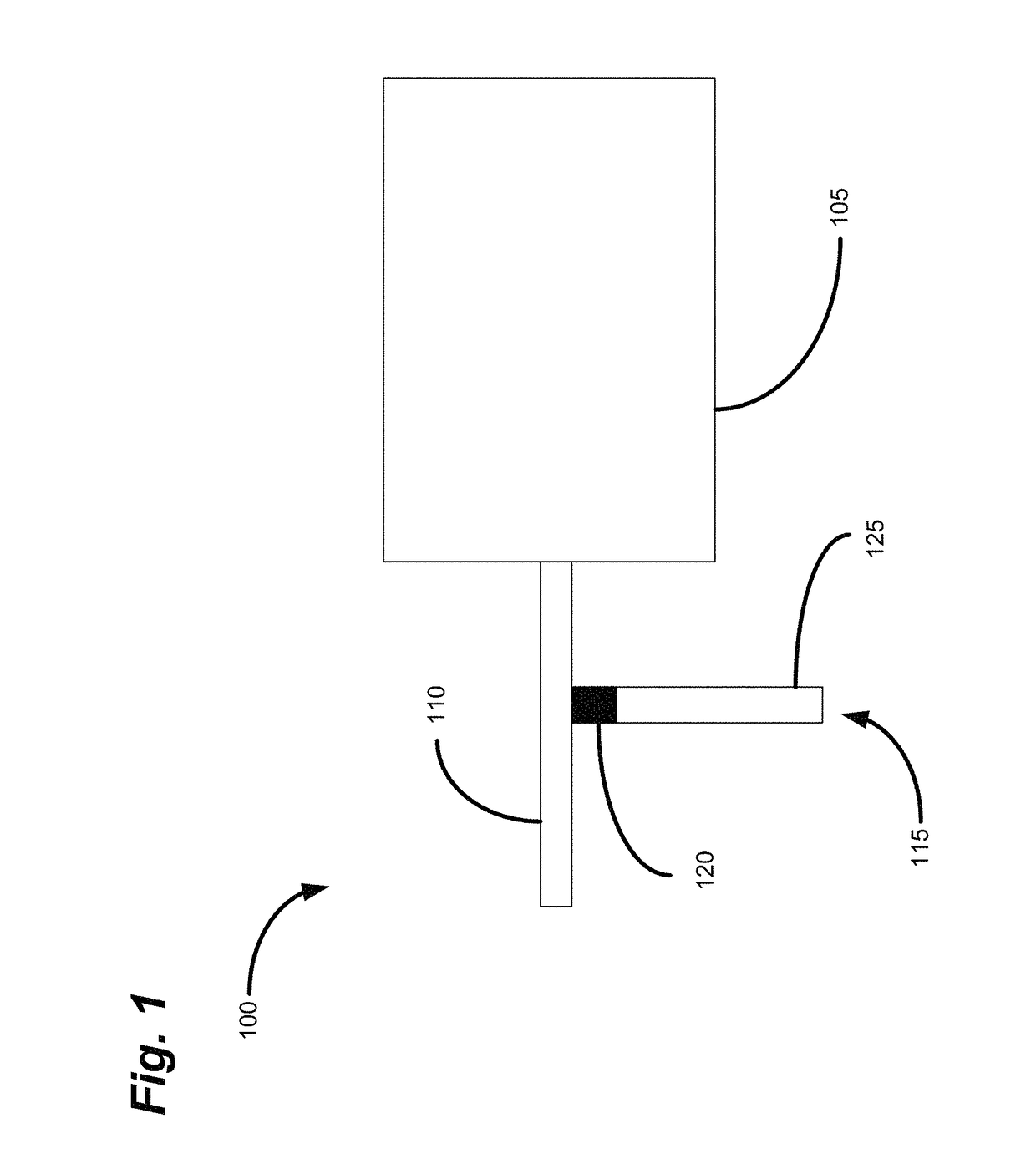
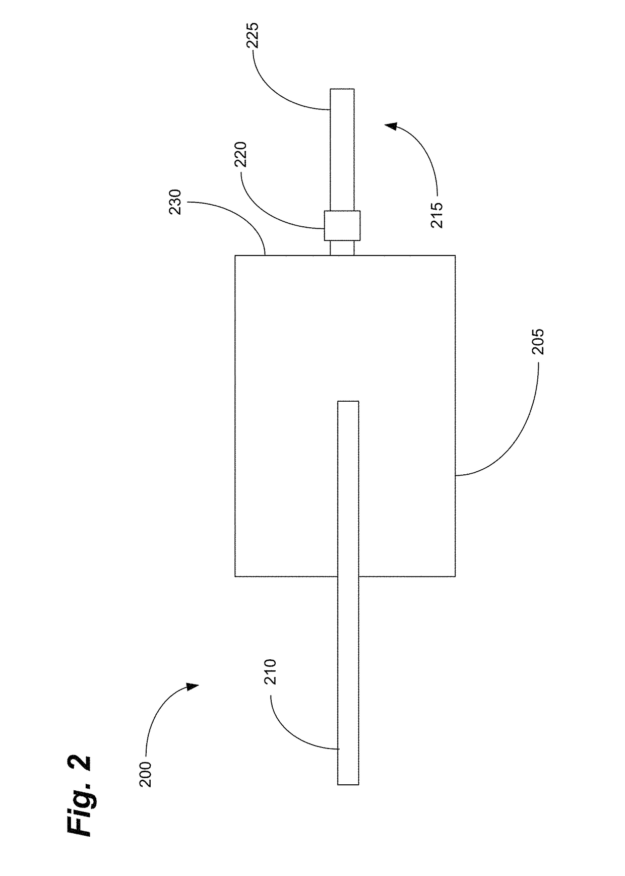
[0012]In some embodiments, the CNTs can be modified to provide sensitivity to a particular analyte. In some embodiments, the sensor can be configured to detect ammonia. In this configuration, the CNTs can be single walled nanotubes (SWNTs) that have been modified using covalent bonding with poly(m-aminobenzene sulfonic acid) (PABS). In this configuration, the change in impedance of the CNT sensor as the result of adsorption of ammonia molecules can result in an easily measurable shift in resonant frequency of the circuit. In addition to providing a measurable shift in resonant frequency, the integrated antenna system can enable duplex communication to / from the sensor circuit to enable low-cost wireless sensing.

Problems solved by technology

Conventional CNT-based gas sensors, which generally rely on detecting either a change in the resonant frequency or change in the amplitude upon exposure to the analyte of interest, provide insufficient sensitivity for many applications.
Unfortunately, minimal frequency shifts have been detected (approximately 5-MHz), even in the presence of high ammonia concentration (e.g., up to 1000 ppm).
While these shifts are detectable in a laboratory setting, in a remote sensing mode, such small detection shifts can lead to false alarms.
Indeed, variances in the resonator fabrication due to manufacturing tolerances may cause changes of the same magnitude.
Furthermore, the large losses in the resonator, caused by CNT loading, limit sensor sensitivity and preclude effective integration of wireless transmission devices such as antennas.
As a result, these configurations are not suitable for low-cost and / or wireless applications for standoff sensing, for example.
Again, due to very small variation in the dielectric constant upon exposure to gas, however, this sensor also suffers from low sensitivity, thus limiting its practical uses.
Unfortunately, this method is susceptible to interference and noise, which can also lead to false readings.

Method used


Image

  • Highly sensitive standoff gas sensing using carbon nanotubes and integrated wireless devices
  • Highly sensitive standoff gas sensing using carbon nanotubes and integrated wireless devices
  • Highly sensitive standoff gas sensing using carbon nanotubes and integrated wireless devices

Examples


example 1

[0051]In some embodiments, a PABS-SWNT solution in water can be prepared for printing CNTs on the substrate. In solid form, however, SWNTs are highly entangled and associated in macroscopic bundles. To disperse these bundles in water, therefore, requires significant effort to break the bundles and dissolve the material. To this end, a portion of material can be sonicated in water.

[0052]In some embodiments, PABS-SWNT powder, of the type sold by Carbon Solutions Inc., Riverside, Calif., for example, can be used to prepare a gas sensing film 120, 220 that is reactive in the presence of ammonia (NH3).5 Aqueous dispersions of PABS-SWNT with a concentration of approximately 5 mg / mL in water can be prepared, for example, by ultrasonication, or other suitable method, followed by deposition onto a paper substrate using, for example and not limitation, ink jet printing, spin coating, or screen printing. Controlled multiple layers of PABS-SWNT can be applied in each fabrication to assure the r...

example 2

[0068]A DMP-2800 tabletop inkjet printer is available from Dimatix, Inc., Santa Clara, Calif.6 To ensure good RF properties of the final product, an in-house recipe was developed taking into account all of the aforementioned parameters that affect the print quality. For all RF traces, such as the patch antenna, Dimatix 1-pL silver nanoink cartridges (DMC-11601) are kept at a distance of 0.5 mm from the surface of the paper. The printer head is first adjusted to achieve a print resolution of 2540 dpi, which ensures good RF conductivity (i.e., approximately 9×10⁶ S / m), up to several gigahertz. Conductive ink CCI-300 from Cabot Corporation, Billerica, Mass.,7 is then jetted through the cartridges at a temperature of 40° C., with the paper substrate maintained at 60° C. Each printed device is then cured in a thermal oven for approximately 2 h at 120° C. 6 www.dimatix.com7 www.cabot-corp.com

Paper Characterization

[0069]Embodiments of the present invention can also comprise a measurement-b...

example 3

[0070]The paper substrate was cured first in a thermal oven for 2 h at 120° C. to mimic the curing process of the printed ink. The results for the extracted relative permittivity of the 10-mil-thick cured paper are shown in FIG. 8a. The measured dielectric loss tangent values were bounded between 0.06-0.07 up to 10 GHz.

Silver Ink Characterization

[0071]The conductivity of the printed conductive ink can be measured in an number of ways, including, for example and not limitation, using a Signatone four-point probe.9 To ensure consistency and good RF conductivity, multiple layers of ink can be printed. 9 www.signatone.com.


PUM

PropertyMeasurementUnit
resonance frequencyaaaaaaaaaa
resonance frequency shiftaaaaaaaaaa
resonance frequencyaaaaaaaaaa

Abstract

A gas sensor utilizing carbon nanotubes (CNTs) is disclosed. The sensor can include a patch antenna, a feed line, and a stub line. The stub line can include a carbon nanotube (CNT) thin-film layer for gas detection. The CNTs can be functionalized to detect one or more analytes with specificity designed to detect, for example, environmental air contaminants, hazardous gases, or explosives. The sensor can provide extremely sensitive gas detection by monitoring the shift in resonant frequency of the sensor circuit resulting from the adsorption of the analyte by the CNT thin-film layer. The sensor can be manufactured using inkjet printing technologies to reduce costs. The integration of an efficient antenna on the same substrate as the sensor enables wireless applications of the sensor without additional components, for wireless standoff chemical sensing applications including, for example, defense, industrial monitoring, environmental sensing, automobile exhaust analysis, and healthcare applications.

Description

CROSS REFERENCE TO RELATED APPLICATIONS[0001]This Application claims priority to, and benefit under 35 USC §119(e) of, U.S. Provisional Patent Application Ser. No. 61 / 605,362, entitled “Highly Sensitive Standoff Gas Sensing using Carbon Nanotubes,” filed Mar. 1, 2012, which is hereby incorporated by reference as if fully set forth below.BACKGROUND OF THE INVENTION[0002]1. Field of the Invention[0003]Embodiments of the present invention relate generally to gas sensors, and more specifically to highly sensitive gas sensors utilizing carbon nanotubes and integrated antennas for wireless applications.[0004]2. Background of Related Art[0005]Carbon nanotubes (CNTs) are long thin cylinders of carbon with a typical diameter ranging from approximately 1 nm to 100 nm. Carbon nanotubes have a number of advantageous properties including, for example, their size, shape, and physical properties. Due to their large tubular surface area, with a hollow inner core and a thin cylindrical wall, CNTs ex...

Claims


Application Information

Patent Timeline
Patent Type & Authority Patents(United States)
IPC IPC(8): G01N29/036G01N29/24G01N29/02H01G11/36H01L51/00
CPCG01N29/022G01N29/036G01N29/2481D10B2101/122G01N2291/021H01G11/36H01L51/0048H10K85/221
Inventor NAISHADHAM, KRISHNASONG, XIAOJUANWAGNER, BRENT
Owner GEORGIA TECH RES CORP
Learn More