

Embedded button for an electronic device
a technology of electronic devices and buttons, applied in the direction of electronic switching, emergency actuators, pulse techniques, etc., can solve the problems of phone damage and phone breakag
- Summary
- Abstract
- Description
- Claims
- Application Information
AI Technical Summary
Benefits of technology
Problems solved by technology
Method used
Image

Examples
first embodiment
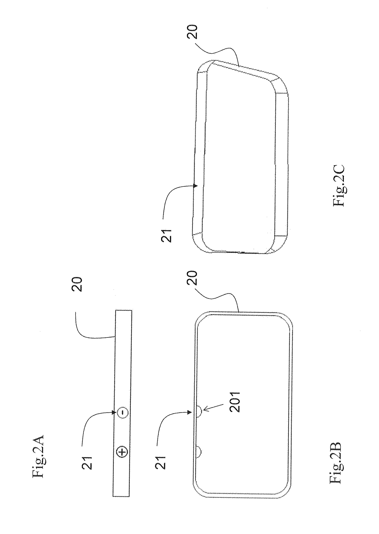
[0024]FIGS. 2A˜2C Show an Outer Frame for a First Embodiment According to the Present Invention
[0025]FIG. 2A shows a side view of a mobile phone
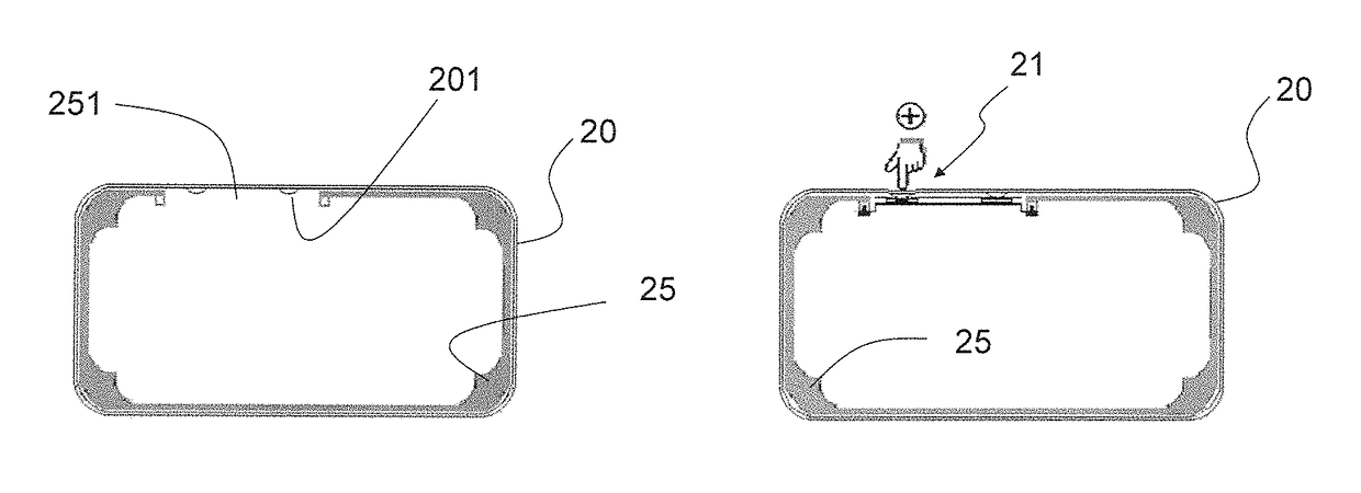
[0026]FIG. 2A shows that an embedded button for a mobile phone has an outer frame 20. A button area 21, a printed mark is shown for indicating a position to press, is configured on an outside surface of the outer frame 20. Since the button area 21 only shows an area to be depressible and no physical button exists, there is no gap surrounding the button area. In other words, there is no gap passing through the outer frame to link the outside and inside of the mobile phone.
[0027]FIG. 2B shows an inner bump configured inside the outer frame
[0028]FIG. 2B shows that an inner bump 201 is aligned with the button area 21 and is configured inside the outer frame 20.
[0029]FIG. 2C shows the outer frame has no gap surrounding the button area.
[0030]FIG. 2C shows that there is no gap surrounding the button area 21; i.e. no gap passing through the outer fr...
second embodiment
[0050]FIGS. 11A˜11B Shows a Second Embodiment According to the Present Invention
[0051]FIG. 11A shows that the inner frame 25 and the outer frame 20 are integrated into a single unit. A bump 202 is formed on top of the pressure switch 253. A chamber 206 is formed in the integrated frame 205. The bump 202 with the pressure 253 is inserted into the chamber 206 from a lateral side of the frame 205.
[0052]FIG. 11B shows that the bump 202 with the pressure 253 has been seated in the chamber 206.
[0053]FIGS. 12A˜12B Shows a Second Embodiment According to the Present Invention
[0054]FIG. 12A shows that an embedded button for an electronic device includes a top plate 520. A button area 211, a printed mark is shown for instructing a position to press, is configured on a top surface of the top plate 520 without having a gap surrounding the button area 211. An inner bump 501 is aligned with the button area 211 and configured on a bottom surface of the top plate 520. A pressure switch 553 is config...
fourth embodiment
[0056]FIGS. 13A˜13B Shows a Fourth Embodiment According to the Present Invention
[0057]FIG. 13A shows that an embedded button for a an electronic device includes a top plate 520. A button area 211, a printed mark to indicate a position to press, is configured on a top surface of the top plate 520 without having a gap surrounding the button area 211. A pressure switch 553 is configured on bottom of the top plate 520 and aligned with the button area 211. A frame 525 has a recess 526. The top plate 520 and the pressure switch 553 is prepared to be configured in the recess 526. A bump 601 is configured on top of a bottom surface of the recess 526 and aligned with the button area 211. A top of the bump 601 contacts a bottom of the pressure switch 553.
[0058]FIG. 13B shows that the top plate 520, pressure switch 553 have been inserted into the recess 526 from top.
[0059]FIG. 14 Shows a Fourth Structure for the Pressure Switch
[0060]FIG. 14 shows a membrane switch which has a top electrode 263...
PUM
 Abstract
Description
Claims
Application Information