Palpometer

a technology of palpometer and sensitivity, which is applied in the field of palpometer, can solve the problems of inability to meet the needs of all examiners, inability to use commercial esthesiometers or electronic pressure algometers, and lack of accuracy and repeatability of manual palpation, so as to improve the palpation procedure for touch, the effect of high repeatability and convenient application

Active Publication Date: 2017-09-19
SUNSTAR SUISSE SA
View PDF17 Cites 1 Cited by
  • Summary
  • Abstract
  • Description
  • Claims
  • Application Information

AI Technical Summary

Benefits of technology

[0006]A method for applying a selected and repeatable force against a patient's body using a manually actuated palpometer device (10) set forth in the present disclosure requires first placing the proximal end (16) of the palpometer probe (14) in contact with a selected area on the patient's body. Grasping the palpometer housing (12) in one hand, an examiner places a thumb over the axial opening (28) in the distal axial face (30) of the housing, urging the housing axially towards the patient's body with a bias force. As the bias force on the housing is increased, the internally contained bias spring (24) is compressed between the housing and the annular flange (22) on the probe, and the distal end (26) of the probe is displaced towards the axial opening (28) in the distal axial face. Upon application of the predetermined amount of bias force, the distal end (26) of the probe is displaced to a position which is flush with the distal axial face (30) of the housing (12), providing the examiner with a tactile sensation to the thumb. By relying upon the tactile sensation caused by the displacement of the distal end (26) of the probe (14), the examiner can maintain the predetermined amount of bias force against the patient's body, and may easily apply repetitions of the same predetermined amount of bias force as required during testing of the patient's tactile or pain sensitivity, or to establish stimulus-response functions on the temporalis and masseter muscles and on the temporomandibular joint.

Problems solved by technology

Manual palpation may lack accuracy and repeatability, as the examiner may not be able to provide consistent applications of pressure at various locations on the patient's body.
The use of commercial esthesiometers or electronic pressure algometers requires expensive equipment which may not be available to all examiners.

Method used


Image

  • Palpometer
  • Palpometer
  • Palpometer

Examples


Embodiment Construction

[0023]The following detailed description illustrates the invention by way of example and not by way of limitation. The description enables one skilled in the art to make and use the present disclosure, and describes several embodiments, adaptations, variations, alternatives, and uses of the present disclosure, including what is presently believed to be the best mode of carrying out the present disclosure.

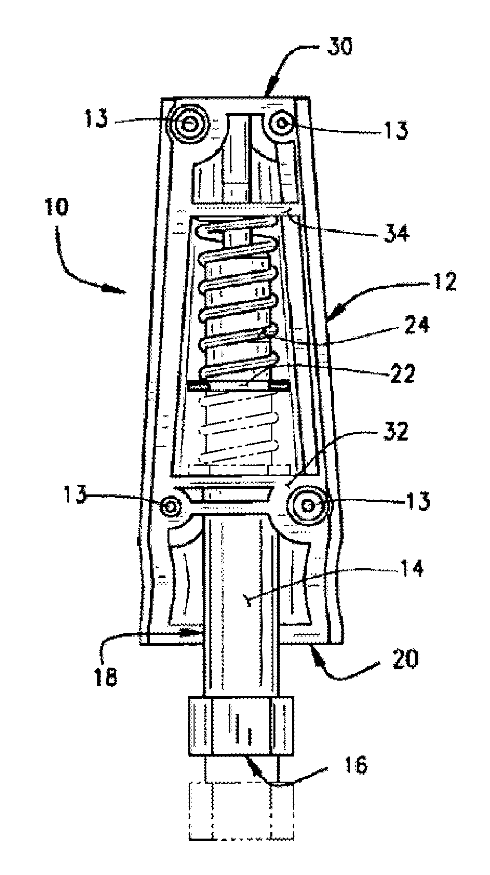
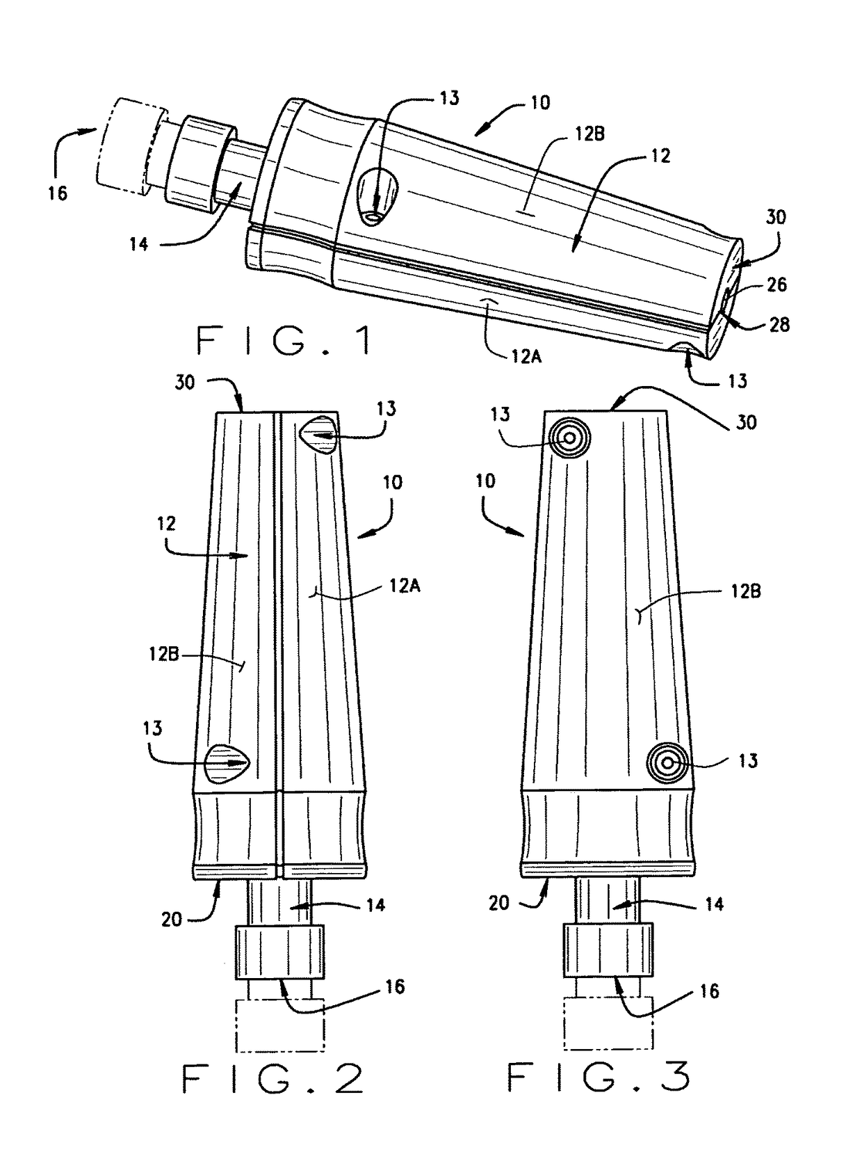
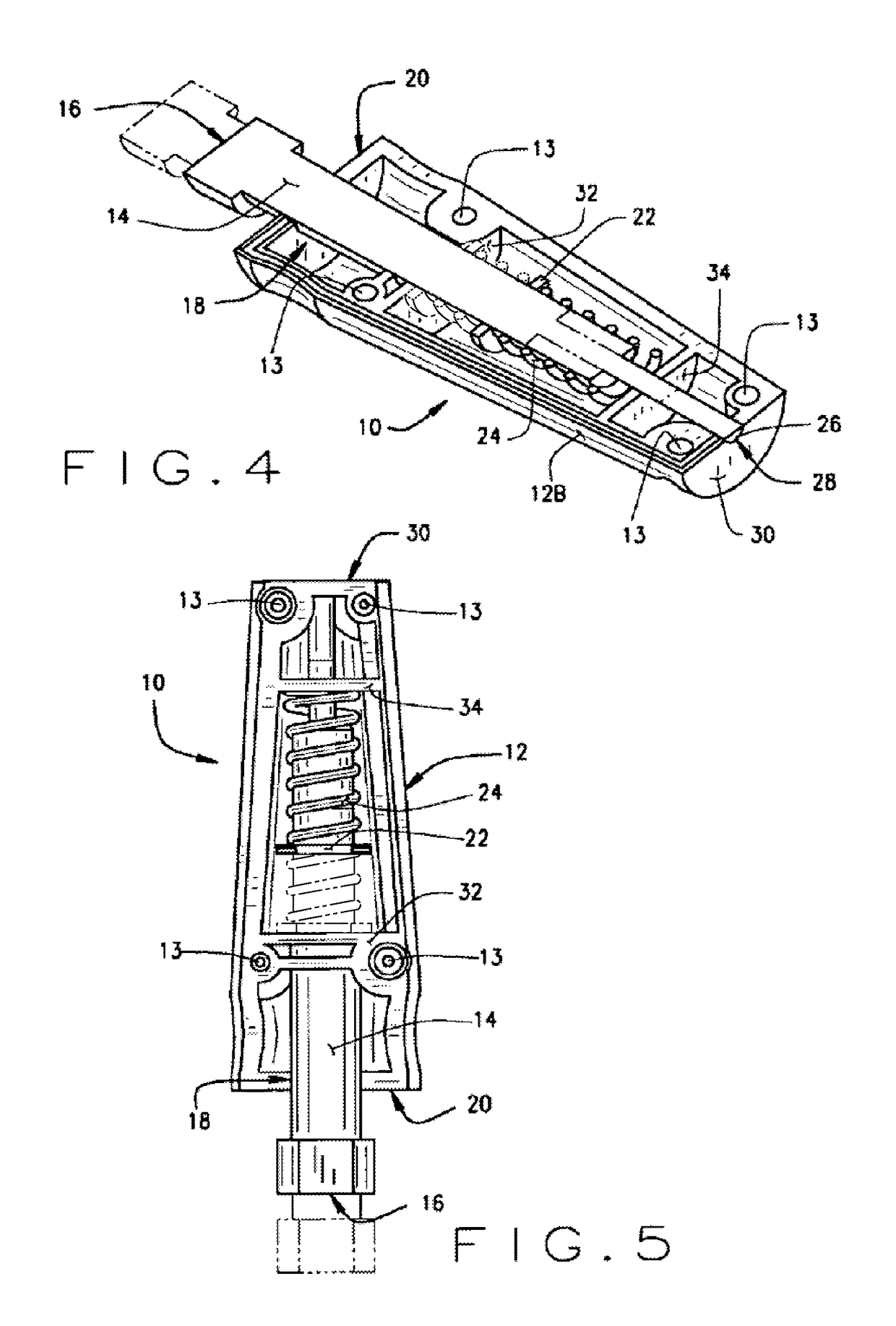
[0024]Turning to the Figures, a palpometer device (10) of the present disclosure for assisting an examiner to evaluate deep pain sensitivity in a patient is shown generally. The palpometer device (10) consists of a housing (12) internally supporting an axially displaceable spring-biased probe (14) for axial displacement through openings (18, 28) at opposite axial ends of the housing. The housing preferably has outer dimensions which are sized for a comfortable one-handed grip by an examiner, such as a cylindrical form (10) shown in FIGS. 1-5, or an alternate rounded rectangular form...


PUM


Abstract

A palpometer device for assisting an examiner to evaluate deep pain sensitivity in a patient includes a housing supporting an axially displaceable spring-biased probe having a proximal end extending from an axial bore in a proximal axial face of the housing, and adapted for abutting contact with the patient. Within the housing, the spring-biased probe incorporates an annular flange for engaging one end of a bias spring coaxially disposed within the housing. The bias spring is disposed coaxially about the probe to resist axial displacement of the housing towards the proximal end of the probe upon manual application of a bias force to the housing, when the proximal end of the probe is in contact with a patient's body.

Description

CROSS-REFERENCE TO RELATED APPLICATIONS[0001]The present application is the U.S. national stage of PCT / DK2011 / 050006 filed Jan. 7, 2011, which claims priority of U.S. Provisional Patent Application Ser. No. 61 / 293,299 filed on Jan. 8, 2010, and which is herein incorporated by reference.BACKGROUND OF THE INVENTION[0002]The present application is related to methods and apparatus for the assessment of deep pain sensitivity in a patient, and in particular, to a manually actuated palpometer utilized to establish stimulus-response functions on the temporalis and masseter muscles and on the temporomandibular joint using a spring-biased probe configured to provide a uniform and repeatable stimulation to a patient.[0003]Reliable assessment of deep pain sensitivity is needed for accurate diagnoses of patient sensitivity such as by dentists evaluating temporomandibular disorders (TMD) or doctors evaluating arthritis. Current methods and procedures rely either upon manual palpation by an examin...

Claims


Application Information

Patent Timeline
Patent Type & Authority Patents(United States)
IPC IPC(8): A61B5/00A61B5/103
CPCA61B5/4827A61B5/0053A61B5/103A61B5/4824A61B5/4528A61B2560/0425
Inventor SVENSSON, PETERRAVNHOLT, GERT
Owner SUNSTAR SUISSE SA
Why Eureka
Try Eureka