Activity frame

a technology of activity frame and frame, which is applied in the field of activity frame, can solve the problem of limited play value of such a fram

Inactive Publication Date: 2017-09-19
WATERMAN MARK JULIAN
View PDF19 Cites 10 Cited by
  • Summary
  • Abstract
  • Description
  • Claims
  • Application Information

AI Technical Summary

Benefits of technology

[0011]In a first configuration the inner ring has a sphere mounted inside, so that the inner ring is round a circumference of the sphere. The sphere has an opening which may be closed and by which individuals can enter or leave the sphere. In this configuration movement of an individual within the sphere causes the inner and middle rings to rotate with respect to one another and in respect to the outer ring, allowing the sphere to undertake tumbling-like motions.
[0012]In a second configuration the inner ring has a cylindrical tub or barrel mounted therein with the inner ring being a circumference of the cylindrical tub or barrel, the outer ring is fixed in relation to the supports and the inner ring is fixed in relation to the middle ring. The cylindrical tub or barrel has an opening which may be closed by which an individual may enter of leave the cylindrical tub or barrel. In this configuration movement of an individual within the cylindrical tub or barrel causes middle rings to rotate with outer ring, allowing the cylindrical tub or barrel to rotate.
[0019]In each of the configurations attachments are demountable. In this way the basic three ring configuration can be adapted readily from one configuration to another. In this way a single frame can be set up for a variety of different activities.

Problems solved by technology

However the play value of such an activity frame is limited in terms of the variety of activities that can be undertaken.

Method used


Image

  • Activity frame
  • Activity frame
  • Activity frame

Examples


Embodiment Construction

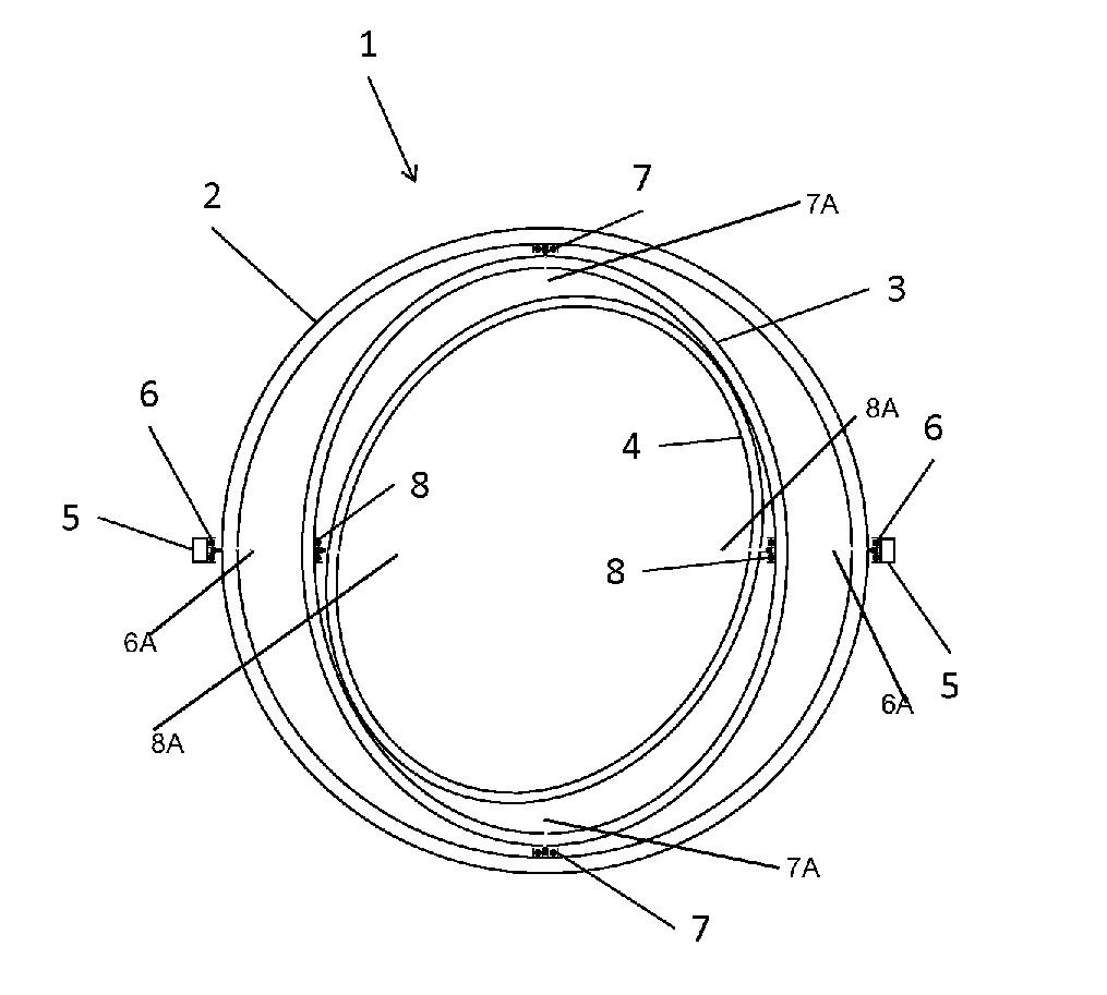
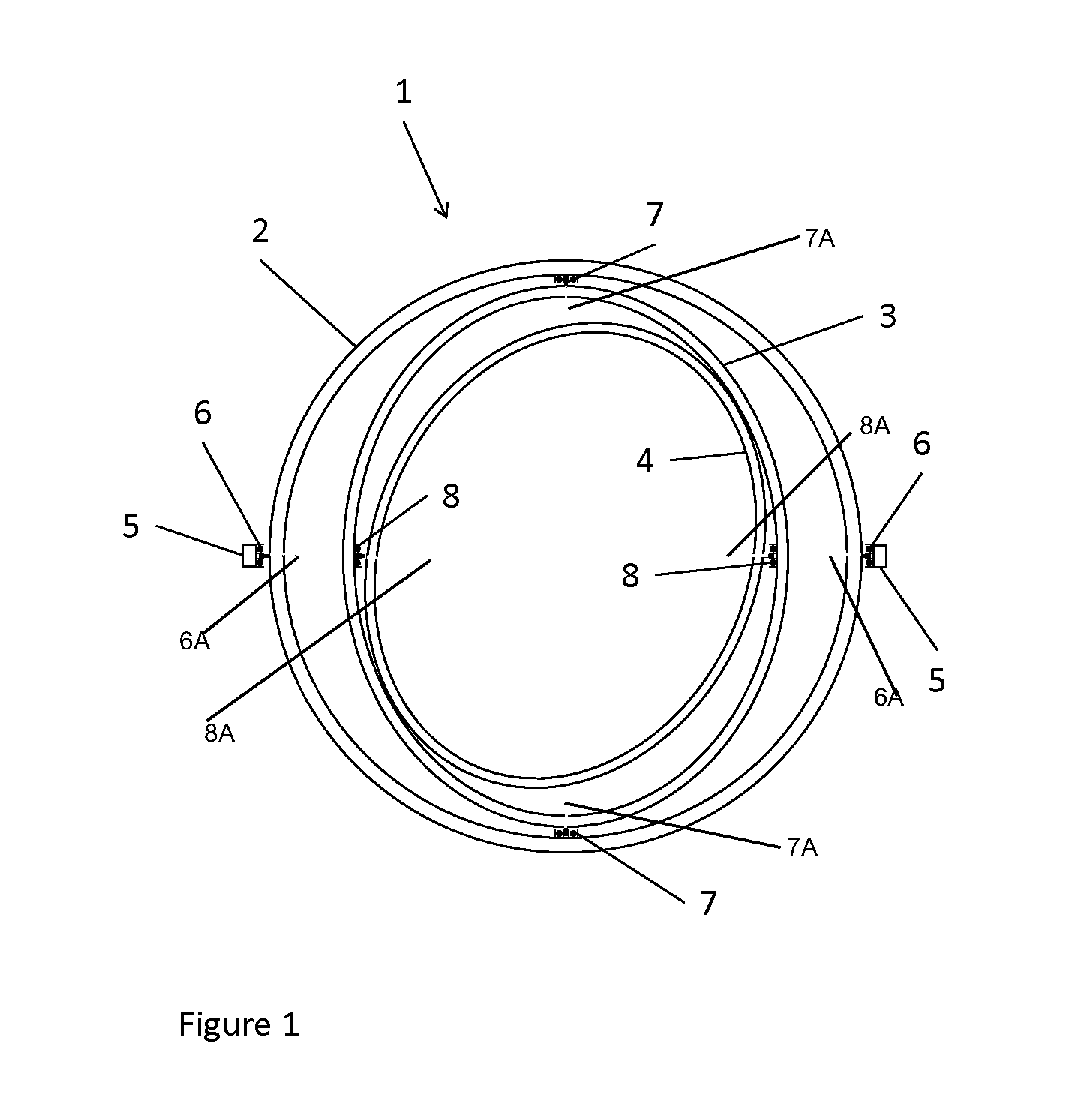
[0039]In FIG. 1, an activity frame 1 comprises three concentric rings, a first or outer ring 2, a second or middle ring 3, and a third or inner 4. The first or outer ring 2 is mounted between a pair of opposed bearings 6 in an opposed pair of supports 5; the first bearings 6 having a first common axis 6A. The second or middle ring 3 is mounted between opposed bearings 7 on the first ring 2; the bearings 7 having a second common axis 7A orthogonal to the first common axis 6a. The third or inner ring 4 is mounted between opposed bearings 8 on the second ring; the bearings 8 having a third common axis 8A orthogonal to the second axis 7A. The pair of opposed supports may be upstanding members of a frame or mounted separately in the ground.

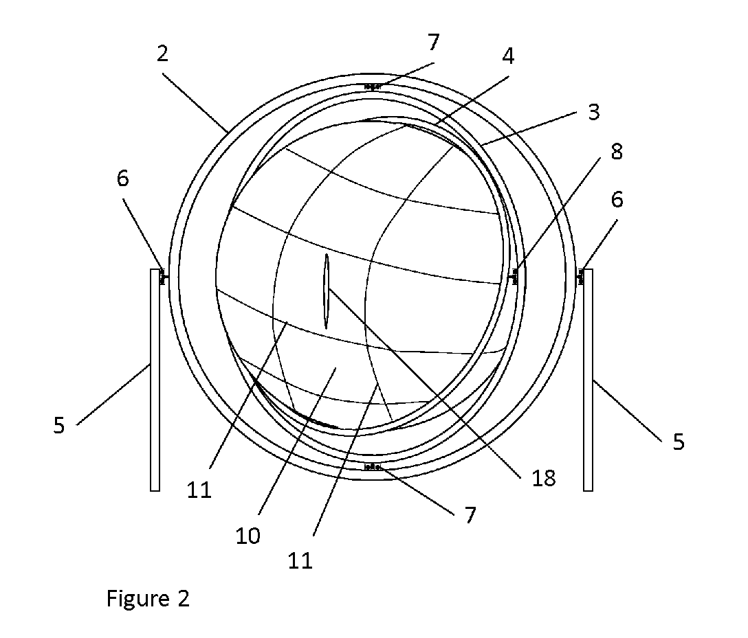
[0040]In FIG. 2 the inner ring 4 has a sphere 10 mounted inside, so that the inner ring 4 is round a circumference of the sphere 10. The sphere 10 is of a soft but strong deformable material such as padded nylon, for safety, supported in shape by a wir...


PUM

PropertyMeasurementUnit
spherical shapeaaaaaaaaaa
tensionaaaaaaaaaa
movementaaaaaaaaaa

Abstract

An activity frame comprising a first or outer ring mounted between a pair of opposed bearings in a opposed pair of supports, for example upstanding members of a frame, the first bearings having a having a first common axis; a second or middle ring mounted between opposed bearings on the first ring, the bearings having a second common axis orthogonal to the first common axis; a third or inner ring mounted between opposed bearings on the second ring, the bearings having a third common axis orthogonal to the second axis provided with demountable restraining means to limit the movement of two or more of the rings and demountable bars to fix one or more of the rings to the frame or other fixed object.

Description

[0001]This application is the U.S. national phase of International Application No. PCT / GB2014 / 051996 filed 1 Jul. 2014 which designated the U.S. and claims priority to GB Patent Application No. 1312167.8 filed 7 Jul. 2013, the entire contents of each of which are hereby incorporated by reference.TECHNICAL FIELD[0002]This invention relates to an activity frame. Its primary application is as a children's play frame, but a stronger unit could be used for adult keep-fit activities or for adult or children's restorative and recuperation activities.BACKGROUND ARTPTL 0001: U.S. Pat. No. 4,799,667 A (GYROTECH CORPORATION). 1989 Jan. 24;PTL 0002: GB 325190 A (FRIED). 1930 Feb. 11; andPTL 0003: WO WO 00 / 20083 A (GEURTS). 2000 Apr. 13,[0003]for example, describe activity frames comprising three concentric rings: a first or outer ring mounted between a pair of opposed bearings in a opposed pair of supports, for example upstanding members of a frame, the first bearings having a having a first co...

Claims


Application Information

Patent Timeline
Patent Type & Authority Patents(United States)
IPC IPC(8): A63B19/04A63G1/08B01J19/00B01L3/00G01N33/487A63B21/00A63G1/14
CPCB01L3/5088G01N33/48721A63B19/04A63B21/4049A63G1/08A63G1/14B01J19/0046B01J2219/00313B01J2219/00317B01J2219/00351B01J2219/00585B01J2219/00659B01J2219/00734B01J2219/00736B01L2200/0642B01L2400/086A63B19/00
Inventor WATERMAN, MARK JULIAN
Owner WATERMAN MARK JULIAN
Why Eureka
Try Eureka