Process chamber gate valve

a gate valve and process chamber technology, applied in the field of gate valves, can solve the problems of high manufacturing cost and complicated construction of the gate valve, and achieve the effects of preventing mechanical abrasion impurities, preventing interference, and reliable structur

Active Publication Date: 2017-09-19
PRESYS
View PDF9 Cites 4 Cited by
  • Summary
  • Abstract
  • Description
  • Claims
  • Application Information

AI Technical Summary

Benefits of technology

[0017]The present invention is advantageous in the way that there is provided only one driving unit, thus obtaining a reliable structure, and a closing operation may be performed in such a way that the valve plate is moved from an opening position to an intermediate position in a vertical direction, and then is moved from its intermediate position to a closing position in a horizontal direction which is vertical with respect to the vertical direction or an opening operation may be performed in the sequence reverse to the above mentioned sequence. It is possible to prevent any interference with a variety of components installed in the interior of the gate valve and prevent impurities from mechanical abrasion from entering the process chamber, thus obtaining efficient operations.

Problems solved by technology

The vacuum valve of the patent document 2 is very efficient in its operative passageway; however for the sake of such an operation, it requires a vertical drive apparatus and a horizontal drive apparatus, and its construction is complicated, and manufacture cost is high.

Method used


Image

  • Process chamber gate valve
  • Process chamber gate valve
  • Process chamber gate valve

Examples


Embodiment Construction

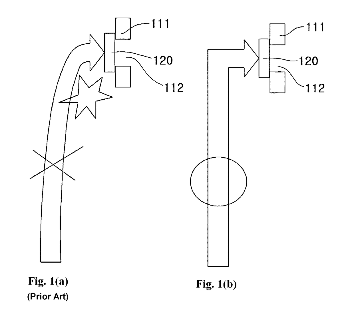
[0025]Now referring to drawings in FIGS. 1-7, there is seen in the figures a gate valve according to an exemplary embodiment of the present invention will be described with reference to the accompanying drawings. In the drawings, it is noted that the same components or parts will be given the same reference numbers. In the course of the description of the present invention, the detailed descriptions on the related functions or construction will be omitted in order to prevent the subject matters of the present invention from becoming ambiguous.

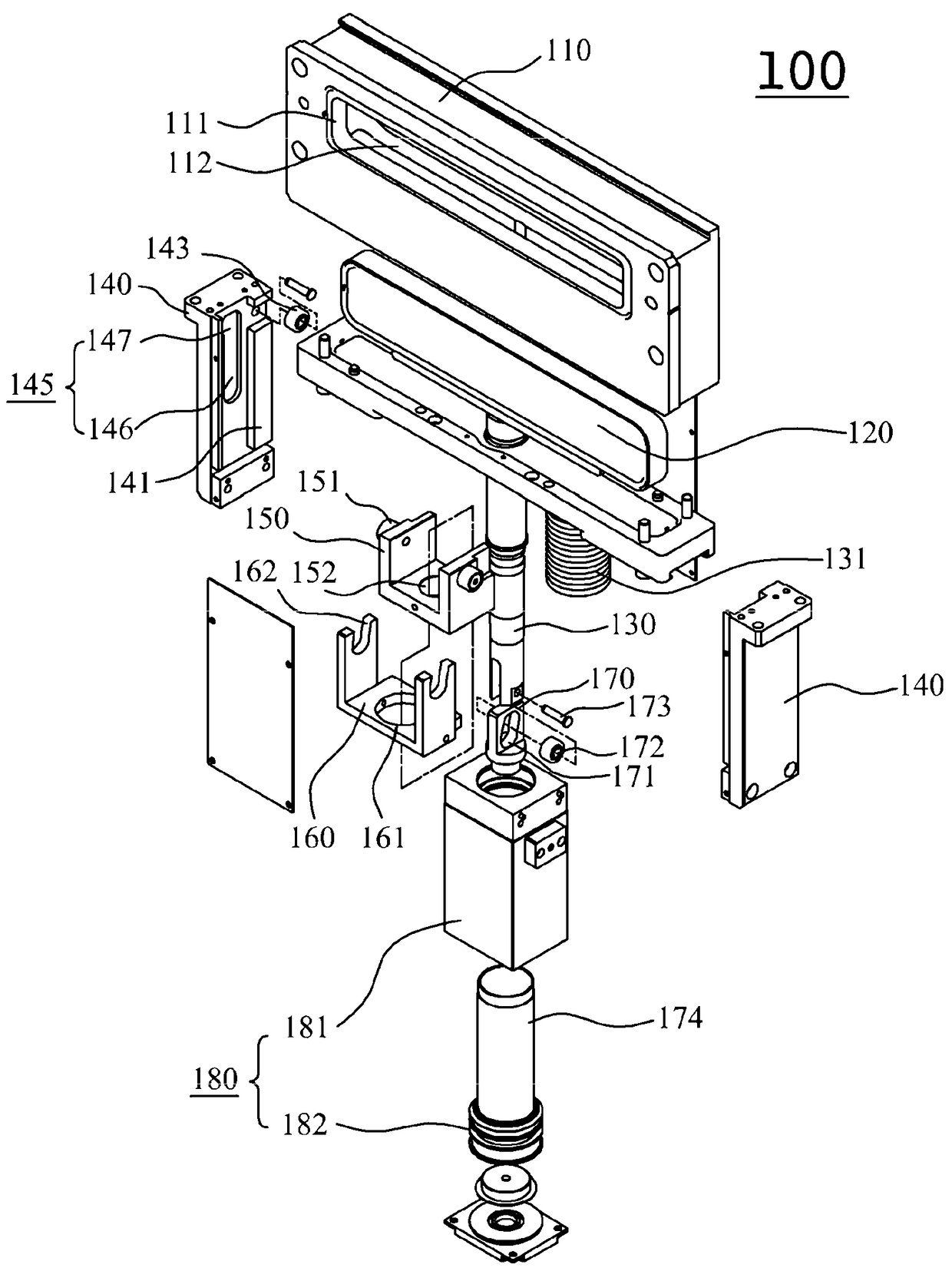
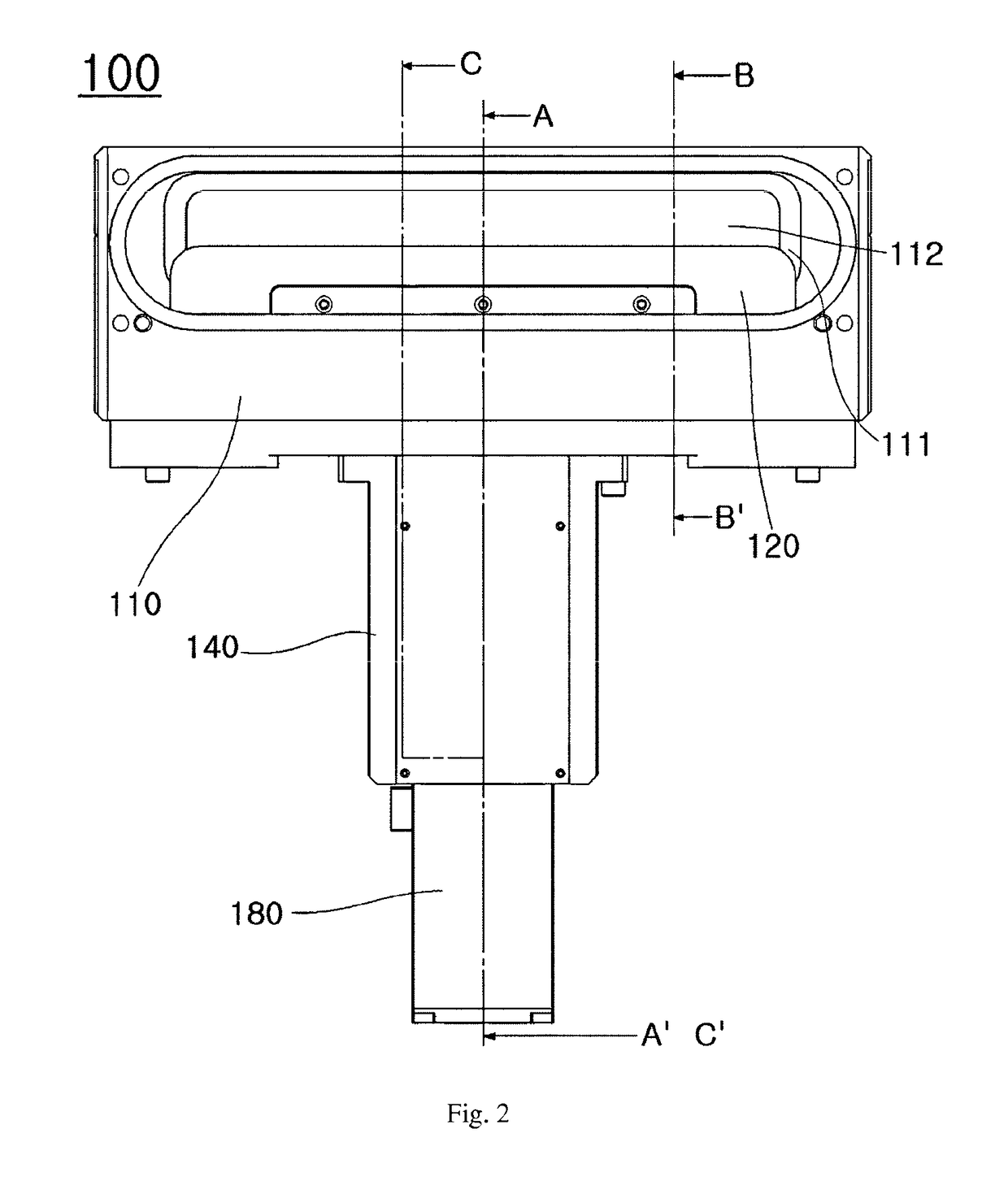
[0026]The gate valve according to the present invention, as illustrated in FIGS. 3 and 4, comprises a valve blade 120, a valve rod 130, a guide housing 140, an L-motion block 150, a cam block 160, a driving rod 170 and an upward and downward driving unit 180.

[0027]The valve blade 120 will be described. The valve blade, as illustrated in FIG. 5, comes into close contact with a valve seat 111 formed around an opening 112 in a valve housing 110 an...


PUM


Abstract

A gate valve for a process chamber includes a valve blade for closure of an opening communicating to the process chamber. The valve blade is employed to seal the opening in a valve housing. The valve blade moves first in a vertical direction and then in a horizontal direction normal to the opening when sealing against the opening. The valve blade moves first in the horizontal direction and subsequently in a vertical direction when disengaging from the opening.

Description

BACKGROUND OF THE INVENTION[0001]1. Field of the Invention[0002]This application is a U.S. National Stage Application based on International Application Number PCT / KR2013 / 002913 filed on Apr. 8, 2013, which claims priority to Korean Application Number 10-2012-0035930 filed on Apr. 6, 2012. Both applications are incorporated herein in their entirety by this reference.[0003]The present invention relates to a gate valve, and in particular to a gate valve 100 which comprises a valve blade 120 which comes into close contact with a valve seat 111 formed around an opening 112 in a valve housing 110 and is configured to close the opening 112 from inside; a valve rod 130 which is connected to the valve blade 120 and sealingly protrudes by way of a bellows 131 from the inside of the valve housing 110 to the outside and which moves in an upward and downward direction and moves in a horizontal direction; a guide housing 140 which is connected to an outer side of the valve housing 110; an L-moti...

Claims


Application Information

Patent Timeline
Patent Type & Authority Patents(United States)
IPC IPC(8): F16K3/18H01L21/677F16K51/02H01L21/67F16K31/122F16K31/524
CPCF16K3/184F16K31/122F16K31/52475F16K51/02H01L21/67126H01L21/67742F16K3/18H01L21/02
Inventor JEE, SHIN-YOUNG
Owner PRESYS
Why Eureka
Try Eureka