Dental implant socket arrangement

a technology for dental implants and sockets, applied in dentistry, dental surgery, medical science, etc., can solve the problems of material welding or shifting within the respective lateral contact surfaces of the allen sockets, the abutment would not fit anymore in the implant, and the production of the above-known implants is more difficult and expensiv

Active Publication Date: 2017-09-26
STRAUMANN HLDG AG
View PDF13 Cites 0 Cited by
  • Summary
  • Abstract
  • Description
  • Claims
  • Application Information

AI Technical Summary

Benefits of technology

[0007]The objective of the invention is to overcome the shortcomings explained above and to provide a, preferably threaded, dental implant with a socket arrangement cooperating with an insertion tool for screwing the implant into the jawbone and acting to keep an abutment in a defined position for a long time, such that a first part of the socket arrangement for positioning the abutment on the implant does not get affected by a second part of the socket arrangement for engaging with the insertion tool forces.
[0009]Advantageously the present invention allows for the engagement between the insertion tool for screwing the dental implant into the jawbone and the dental implant with much longer arm levers in respect to a longitudinal center axis of the implant as compared to a situation in which the outer and coronal surface of the implant had to be milled or lathed for providing another outer socket for an abutment, inasmuch as the outer diameter of the coronal end of the implant is not reduced. The longer arm levers for transmitting necessary forces via second contact surfaces, in order to achieve a certain torque for the screwing in the implant into the jawbone, result in smaller forces at the second contact surfaces. Smaller forces, again, cause less material strain at the second contact surfaces, in particular if the second contact surfaces have an angle perpendicular to the respective resulting force thereat. Alternatively, the second contact surfaces can be devised smaller, for instance, such that resulting notches as cross-sectional shape of the second contact surfaces have a lesser extension in radial direction. Thus both, the second contact surfaces for transmitting the insertion torque from the insertion tool, and first contact surfaces for longtime engaging with the abutment, have a longer arm lever resulting in better force transmission, bigger respective contact surfaces and less welding or deformation of the respective contact surfaces, as compared with smaller arm levers. Longer arm levers can be attained if the implant is not reduced in its outer diameter as is it would be the case if an outer coronal socket is provided.
[0011]Also, by avoiding a lathing or milling of both the coronal lateral surface and a coronal inside of the implant, as required by the prior art, and instead lathing, milling or machining only inside the coronal end of the implant machine, time and cost can be saved.
[0012]Advantageously, according to the invention, the first and the second contact surfaces are arranged at a same height along the longitudinal axis of the implant and close to the coronal end thereof, such as to achieve longer arm levers between the implant and the insertion tool or abutment, respectively. This allows a close and good force and torque transmission between the implant and the insertion tool as well as between the implant and the abutment. Furthermore and in contrast to the prior art, the present invention allows for a minimal ingression into the socket, inasmuch as lateral wall thickness perpendicular to the longitudinal axis of the dental implant is maintained while at the same time a minimal total implant length parallel to the longitudinal axis is offered.
[0013]An octagonal cross-sectional arrangement of the first contact surfaces provides for a particularly advantageous aspect of the invention, as the outer surface of an octagon is larger as compared with a surface of a hexagon with the same height and circumference. Thus, an octagonal cross-sectional socket with the respective eight first contact surfaces has a larger contact area engaging with the abutment than a hexagonal cross-sectional socket and still good enough anti-rotational resistance for the abutment on the implant. By the larger first contact surfaces higher lateral forces between the abutment and the implant can be applied without deforming the implant. In respect to the first contact surfaces a torque force around the longitudinal center axis of the implant is much lower than for the second contact surfaces, as the abutment does not apply a torque as high as the insertion tool does. The torque transmitting surface for the insertion tool increases with the number of notches and respective ridges extending in the longitudinal direction from the respective coronal cross-sectional notches and having the respective second contact surfaces. Thus also a number of up to eight notches can be devised according to the torque for screwing in the implant, and / or according to the material strength and thickness of the remaining coronal lateral sidewall of the implant at the height of the first and second contact surfaces.

Problems solved by technology

During this screwing operation the problem has to be faced that the insertion tool, which is for instance an Allen wrench engaging with an Allen socket as part of the socket arrangement, could cause a material welding or shifting within respective lateral contact surfaces of the Allen socket.
Thus, if the same lateral contact surfaces would be used for the positioning of the abutment and the engagement with the insertion tool, or in other words if the first contact surfaces would be the second contact surfaces, there exists the risk that the abutment would not fit anymore in the implant in the determined position due to changes in the socket.
However, the production of the above known implant is more difficult and expensive, inasmuch one has to mill two totally separate parts of the socket arrangement, once outside and once inside the coronal end of the implant.
The presence of higher contact forces increases the welding risk of the material of the socket and can even influence and cause a deformation of the outer first contact surfaces.
The welding of the socket material or the deformation thereof could lead to a more difficult disengagement between the insertion tool and the implant, as a jamming or gripping may occur, or to a worse or even an impossible engagement between the implant and the abutment.
However, having two longitudinally separate anti-rotational means results in an unfavorable deep socket of the implant, which limits the total possible length of the implant substantially.

Method used


Image

  • Dental implant socket arrangement
  • Dental implant socket arrangement
  • Dental implant socket arrangement

Examples


first embodiment

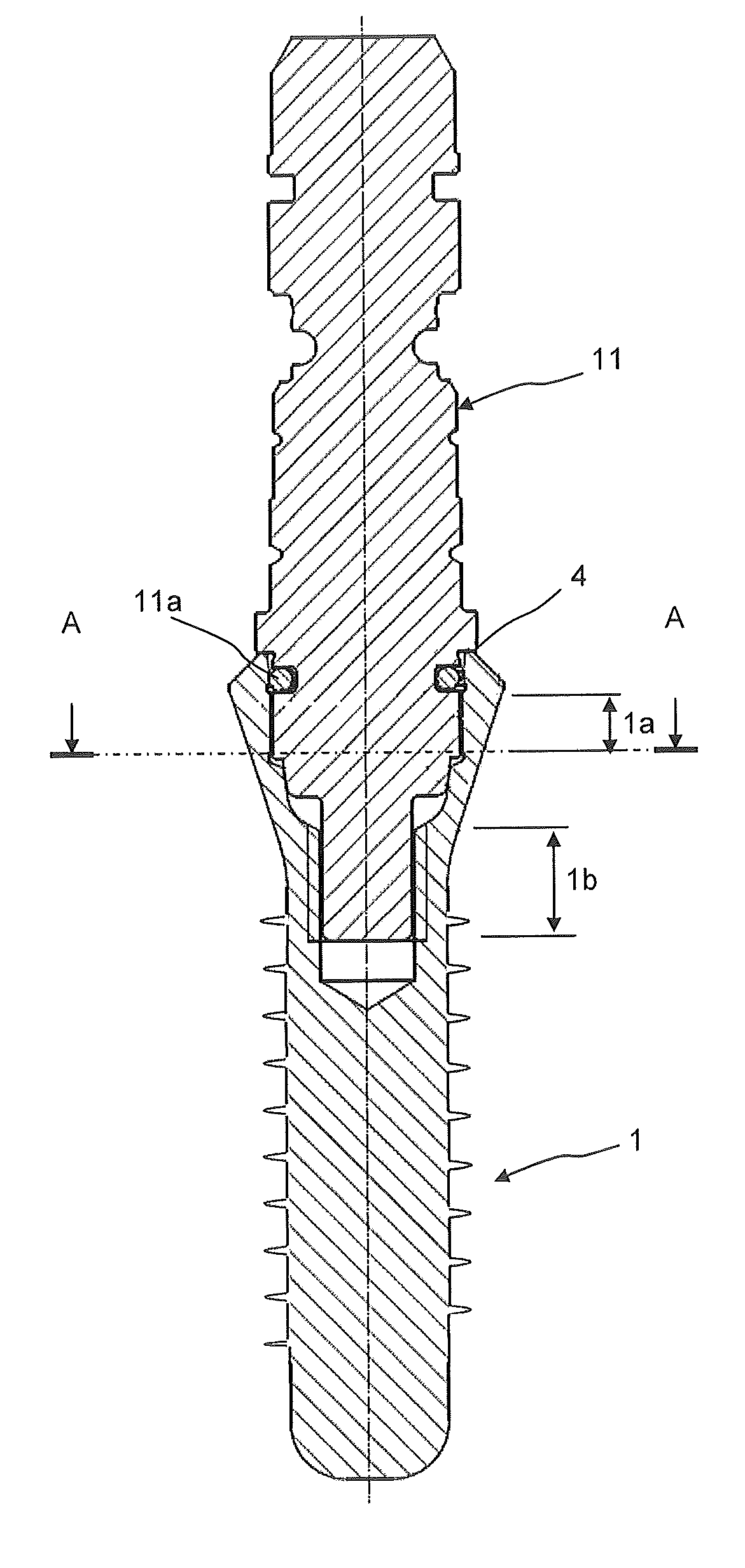
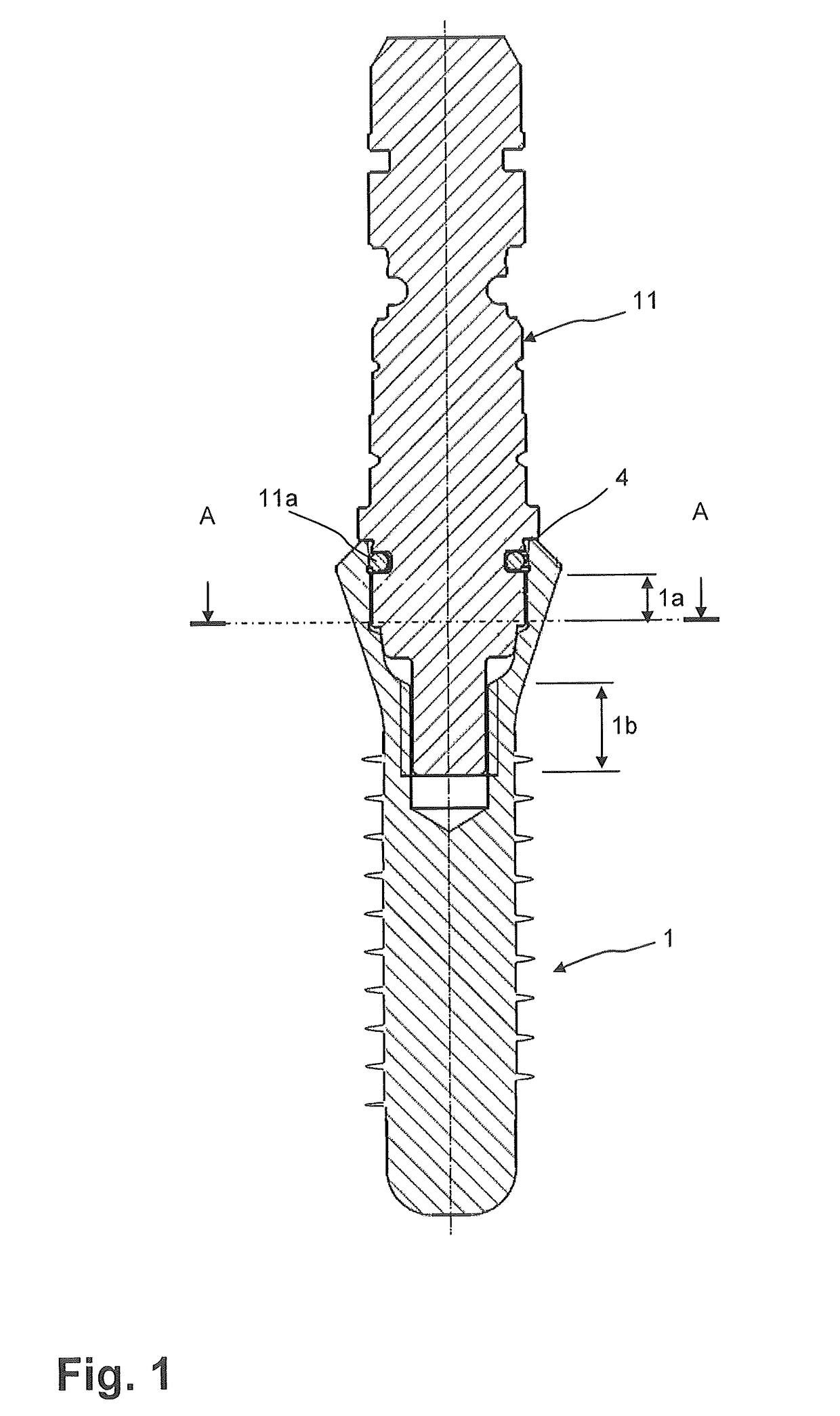
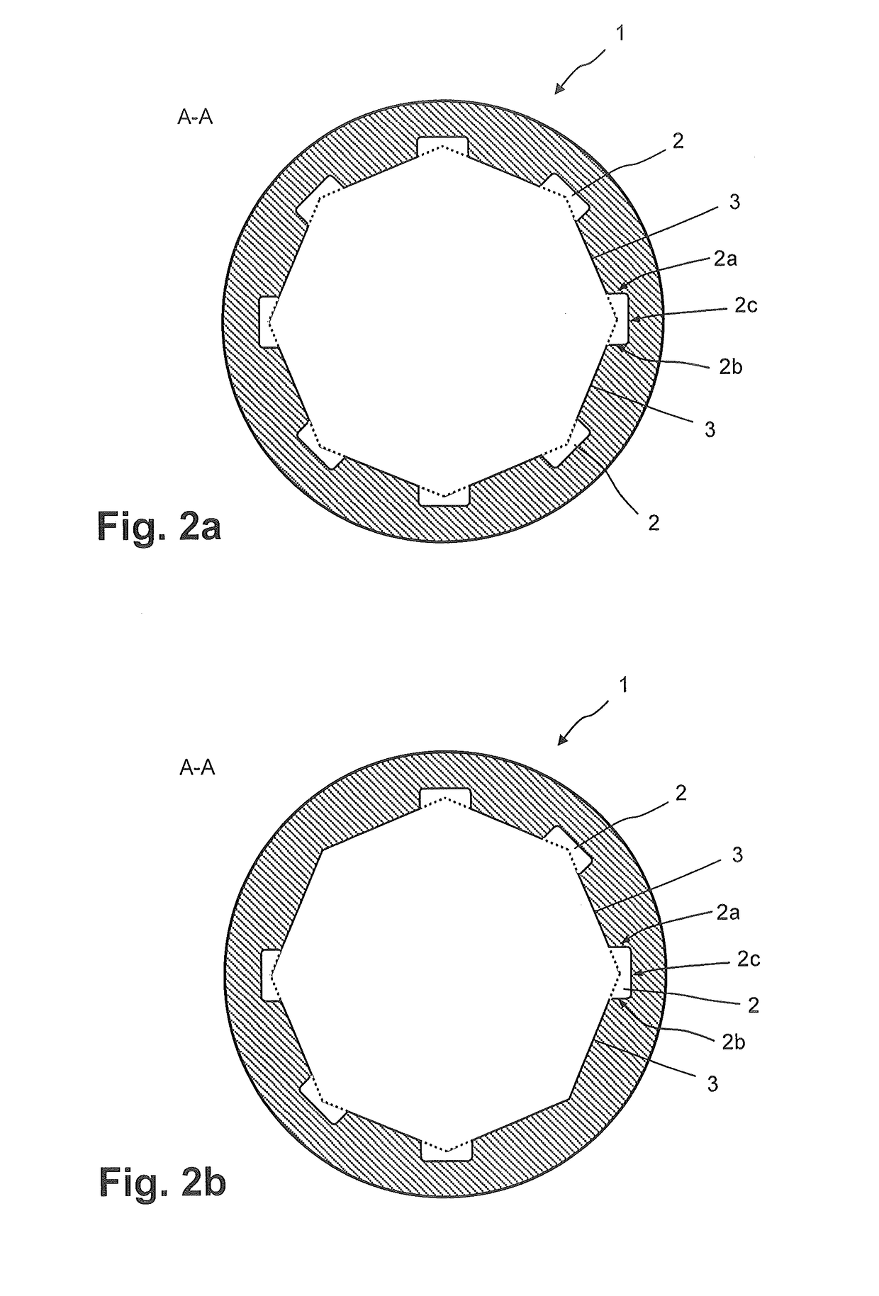
[0034]FIGS. 2a to 2d show variations of the invention along a cross-sectional top view of dental implants taken along line A-A of FIG. 1, which are reduced to the representation of a cross-section of the socket arrangement at the bottom of the first and the second section. For the sake of clarity it should be noted that FIGS. 2a to 5b show cross-sectional discs cut out from the implant 1 perpendicular to its longitudinal axis.

[0035]The first section of the socket arrangement defines first contact surfaces 3 having partly a cross-sectional shape of a polygon and preferably a regular polygon. The first contact surfaces 3 are extending from the coronal end downwardly in apical direction of the longitudinal center axis of the implant 1 along the height 1a of the socket, and are parallel to the longitudinal axis of the implant. Nevertheless, the first contact surfaces 3 may be partly cut out by inclined parts or truncated conical sections 3b, the truncated conical sections (3b) forming p...

third embodiment

[0046]Preferably, in the variations of the third embodiment, the two contact surfaces 2a and 2b are connected by a transition section (not shown) bridging the two surfaces in a way that the no acute angles are existing in the corners between contact surface 2a and 2b. The transition section is preferably curved.

[0047]This arrangement of the second contact surfaces 2a, 2b is less advantageous as compared with the rectangle notches 2 with respect to the forces applied by the ribs of the insertion tool 11. The force vector of torque is not perpendicular to the contact surfaces 2a and 2b, but oriented at a lower angle, which is more unfavorable with respect to jamming / welding of the insertion tool during implant insertion. As compared to the shape of notches 2 or ridges represented in FIGS. 2a to 3d, the shape of the notches 2 or ridges of the embodiments of FIGS. 4a to 4b ensures a minimal removal of material from the original contact surface 3. Therefore, a higher stability of the imp...

fourth embodiment

[0050]Another modified embodiment (not shown) with similar features to those of said fourth embodiment of FIGS. 5a to 5b, but wherein the trapezoidal shape is tapered in radial direction inwardly, is also imaginable. The latter variation has a better perpendicular shape in terms of the applied forces from the ribs of the insertion tool 11. The embodiment with inwardly tapered notches 2 with the second contact surfaces 2a, 2b perpendicular to the applied forces prevent a welding of the contact surfaces which would otherwise weld the contact surfaces if applied with a high tangential component.

[0051]In all described versions of the third and fourth embodiment shown in FIGS. 4a to 5b the angle between contact surface 2a and 2b can range between 30° and 90°, whereby the risk of welding the notches 2 and ridges during torque transmission increases with increasing angle.

[0052]FIGS. 2a to 5b show either four, six or eight notches 2 or ridges either located at sides of contact surface 3 or ...


PUM


Abstract

Dental implant having a socket arrangement having the shape of a regular octagon which is partly interrupted by outwardly extending notches being parallel or parallel and partly inclined with respect to the longitudinal center axis of the implant, the inclination being such as to taper inwardly from their coronal end, wherein interrupting and outwardly extending ridges extending from the notches in an apical direction of the dental implant, first contact surfaces being adapted to engage and rotationally secure an abutment, and wherein second contact surfaces extend from the notches within the ridges in the direction of the longitudinal center axis, the second contact surfaces being adapted to engage with an insertion tool; and wherein the notches are positioned at sides or at corners of the regular octagon.

Description

FIELD OF THE INVENTION[0001]The present invention relates in general to a dental implant intended to be screwed into the jawbone for supporting at least one abutment. The present invention furthermore relates in particular to an improved socket arrangement of the dental implant cooperating on the one hand with an insertion tool and on the other hand with the abutment. Furthermore, the present invention relates to the insertion tool adapted to engage with the socket arrangement of the dental implant.PRIOR ART[0002]As known in the art, a threaded dental implant intended to be screwed into the jawbone for supporting at least one abutment must have a certain socket arrangement with lateral contact surfaces and an upper contact surface whereon the abutment can be fixed for a long time in a determined stable position. Furthermore, as known in the art, the threaded dental implant needs to be screwed into the jawbone with certain torque forces of up to approximately 150 Ncm. During this scr...

Claims


Application Information

Patent Timeline
Patent Type & Authority Patents(United States)
IPC IPC(8): A61C8/00
CPCA61C8/006A61C8/0018A61C8/0022A61C8/0089
Inventor GUENTER, DANIELCOURVOISIER, STEPHANELAZIC, MIODRAGDALLA TORRE, FLORIAN
Owner STRAUMANN HLDG AG
Why Eureka
Try Eureka