Intraocular implant and method for fixing same into an eye

a technology of intraocular implants and eye implants, which is applied in the field of intraocular implants, can solve the problems of difficult to ensure that the lens has the desired placement, difficulty in accurately defining the location of the eye lens in the z-direction, and difficulty in accurately defining the placement of the eye lens, so as to achieve the effect of easy and more secure implant attachment and greater stability of implant attachmen

Active Publication Date: 2017-10-10
STEVENS
View PDF16 Cites 3 Cited by
  • Summary
  • Abstract
  • Description
  • Claims
  • Application Information

AI Technical Summary

Benefits of technology

[0011]It is an aim of the intraocular implant according to the present invention to mitigate drawbacks associated with the known implant techniques.
[0014]The peripheral portion may comprise a short extension of the main portion over the entire periphery of the main portion, the extension of the main portion comprising the at least two lugs. This configuration is potentially more compact than the haptic-based configuration. According to one example embodiment, the lugs are substantially equidistantly spaced around the peripheral portion. This allows for greater stability of attachment of the implant to the capsule.
[0015]The at least two lugs may each comprise a neck portion, which extends from the peripheral portion in the direction substantially perpendicular to the plane of the lamina, and a head portion extending from the neck portion. The head portion may be mushroom-shaped or otherwise larger than the neck portion, which allows for easier and more secure attachment of the implant to the capsule.
[0019]In this method, the at least two lugs may each comprise a neck portion, which extends from the peripheral portion in the direction substantially perpendicular to the plane of the lamina, and a head portion extending from the neck portion, and wherein the lugs are inserted, head portion first, into the voids, the head portion being such as to discourage the implant from coming away from the capsule.

Problems solved by technology

One problem associated with the known capsular insert technique is that it is difficult to centre the lens accurately in the X-Y plane of the eye.
It is also difficult to ensure that the lens has the desired placement in the rotational direction in the X-Y plane.
A third problem is that, due to the presence of the haptics, the known technique requires a fairly large incision in the eye in order to be able to introduce the implant into the eye, whereas it is always desirable to be able to minimize the degree of intervention, including the size of the incision.
A further drawback is the difficulty of accurately defining the location of the lens in the Z-direction.
This can lead to difficulties in defining the required optical power of the lens.

Method used


Image

  • Intraocular implant and method for fixing same into an eye
  • Intraocular implant and method for fixing same into an eye
  • Intraocular implant and method for fixing same into an eye

Examples


second embodiment

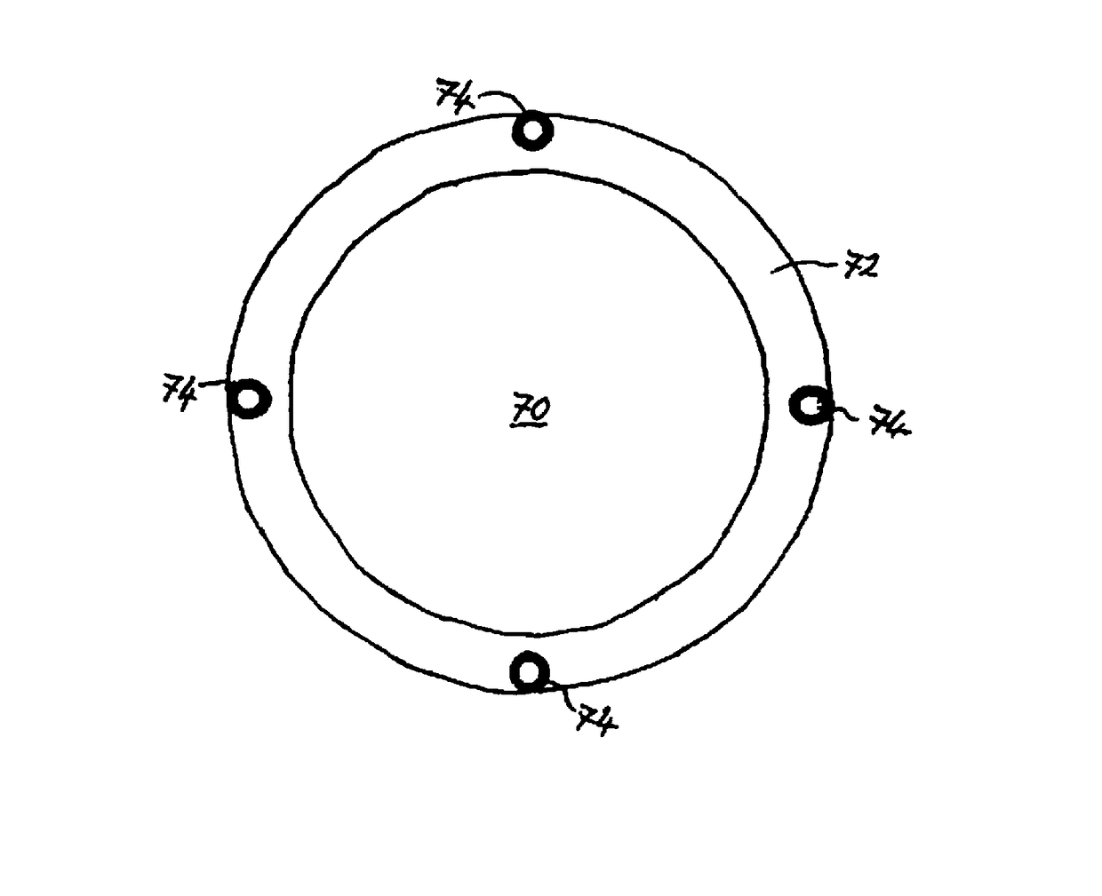
the implant in accordance with the invention is illustrated in FIGS. 10 and 11.

[0036]Here the implant has no haptics, but consists of the optic 70 plus a peripheral section 72, which is a simple extension of the edge of the optic 70. The radial width of the extension will be at least sufficient to accommodate the lugs and to ensure that the voids made in the capsule are reasonably remote from the lip of the capsulotomy. Four lugs 74 protrude from, and are of one piece with, the peripheral section, being substantially equidistantly spaced around the peripheral section. The lugs 74 are configured as in the first embodiment (see FIG. 9).

[0037]This implant is smaller than that of the first embodiment, since no haptics are present. This means that the incision to be made in the eye, in order to introduce the implant into the eye, can be made smaller, with a smaller wound and leading to a faster recovery of the patient and less induced astigmatism.

[0038]When the implant is located adjacen...


PUM


Abstract

An intraocular implant for use in a surgical procedure such as a cataract operation, or in a refractive-lens exchange surgery procedure, has a main portion and a peripheral portion peripheral to the main portion. The main portion is plate-like in shape and may be a lens or a plug for closing an aperture in the capsule of the eye. The implant has two or more lugs extending from the peripheral portion in a direction substantially perpendicular to a plane of the main portion. The lugs extend either from haptics, which protrude from the main portion, or from a short extension of the edge of the main portion. A method for fixing the implant into the eye involves making two or more voids in the capsule wall, offering up the implant to the capsule, so that the lugs lie adjacent to the voids, and inserting the lugs into the voids.

Description

FIELD OF THE INVENTION[0001]The invention relates to an intraocular implant, and in particular to an intraocular implant for use in cataract operations or refractive crystalline lens extraction operations. The invention also relates to a method for fixing such an intraocular implant into an eye.BACKGROUND OF THE INVENTION[0002]The cataract condition is a well known eye ailment, which these days is easily treatable through surgery. The condition involves an opacification, yellowing or clouding of the natural crystalline lens (see FIG. 1), which is situated just behind the iris and serves to focus the incoming image onto the retina at the back of the eye.[0003]The surgical procedure involves the removal of the opaque lens and its substitution by an artificial lens having the required focusing effect.[0004]One way of achieving this is described in U.S. Pat. No. 3,925,825. FIGS. 2 and 3 correspond to FIGS. 1 and 2 of this patent, and show the placing of a lens 10 anterior to the iris 12...

Claims


Application Information

Patent Timeline
Patent Type & Authority Patents(United States)
IPC IPC(8): A61F9/00A61F2/14A61F2/16A61F9/007
CPCA61F9/0017A61F2/14A61F2/16A61F2002/169A61F2/15A61F9/007A61F2002/1681A61F2220/0008
Inventor STEVENS, JULIAN DOUGLAS
Owner STEVENS
Why Eureka
Try Eureka