Method and apparatus for controlling the strip temperature of the rapid cooling section of a continuous annealing line

a technology of rapid cooling and continuous annealing, which is applied in the direction of heat treatment equipment, instruments, furniture, etc., can solve the problems of inability to control the widthwise temperature of the strip, and achieve the effects of excellent effect, excellent effect, and flatness defects in the strip

Active Publication Date: 2017-10-10
POHANG IRON & STEEL CO LTD
View PDF83 Cites 0 Cited by
  • Summary
  • Abstract
  • Description
  • Claims
  • Application Information

AI Technical Summary

Benefits of technology

[0017]In order to accomplish the above objects, the present invention provides a method of uniformly controlling a strip temperature in a rapid cooling section of a continuous annealing line. The method includes the following steps of: determining valve open ratios of lengthwise flow control nozzle blocks and widthwise flow control nozzle blocks, the nozzle blocks spraying mist to front and rear sides of a strip, based on strip temperature measurement values and strip information; determining opening compensation values of the lengthwise flow control nozzle blocks such that the flow rates of the spray mist are adjusted by deducing an actual discharge-side temperature of the strip at every period from a target discharge-side temperature of the strip with respect to the determined valve open ratios; and determining opening values of a plurality of servo valves of the widthwise flow control nozzle blocks such that the flow rates of the spray mist are adjusted in a plurality of areas in a widthwise direction of the strip with respect to the determined valve open ratios, whereby the strip temperature is uniformly controlled through flow rate control over the mist sprayed to the strip, and changes in flatness of the strip are minimized.
[0020]In the method and apparatus for uniformly controlling a strip temperature in a rapid cooling section of a continuous annealing line according to the present invention, a plurality of lengthwise flow control nozzle blocks and a plurality of widthwise flow control nozzle blocks are disposed at front and rear sides of a strip and are divided from each other. The flow rates of mist sprayed from the lengthwise flow control nozzle blocks and the widthwise flow control nozzle blocks are respectively controlled using temperature values measured using the strip center temperature meters and the widthwise temperature meters disposed in the intake side of the rapid cooling section, such that the widthwise temperature distribution of the strip which moves in the vertical direction can have an intended profile. Accordingly, it is possible to achieve an excellent effect in that flatness defects in the strip that would otherwise occur due to non-uniform cooling can be minimized.
[0021]In addition, in the method and apparatus for uniformly controlling a strip temperature in a rapid cooling section of a continuous annealing line according to the present invention, temperature values are measured using the widthwise thermometers in the intake and discharge ends of the rapid cooling section of the continuous annealing line, and the widthwise temperature of the strip can be uniformly controlled through widthwise flow rate control over mist sprayed in the rapid cooling section using the feedback / feedforward control technique. Accordingly, it is possible to achieve an excellent effect in that flatness defects in the strip can be minimized.

Problems solved by technology

However, all of these technologies of the related art are intended to control the lengthwise temperature of the strip, and it is therefore impossible to control the widthwise temperature of the strip.

Method used


Image

  • Method and apparatus for controlling the strip temperature of the rapid cooling section of a continuous annealing line
  • Method and apparatus for controlling the strip temperature of the rapid cooling section of a continuous annealing line
  • Method and apparatus for controlling the strip temperature of the rapid cooling section of a continuous annealing line

Examples


Embodiment Construction

[0030]Hereinafter exemplary embodiments of the present invention will be described in greater detail with reference to the accompanying drawings.

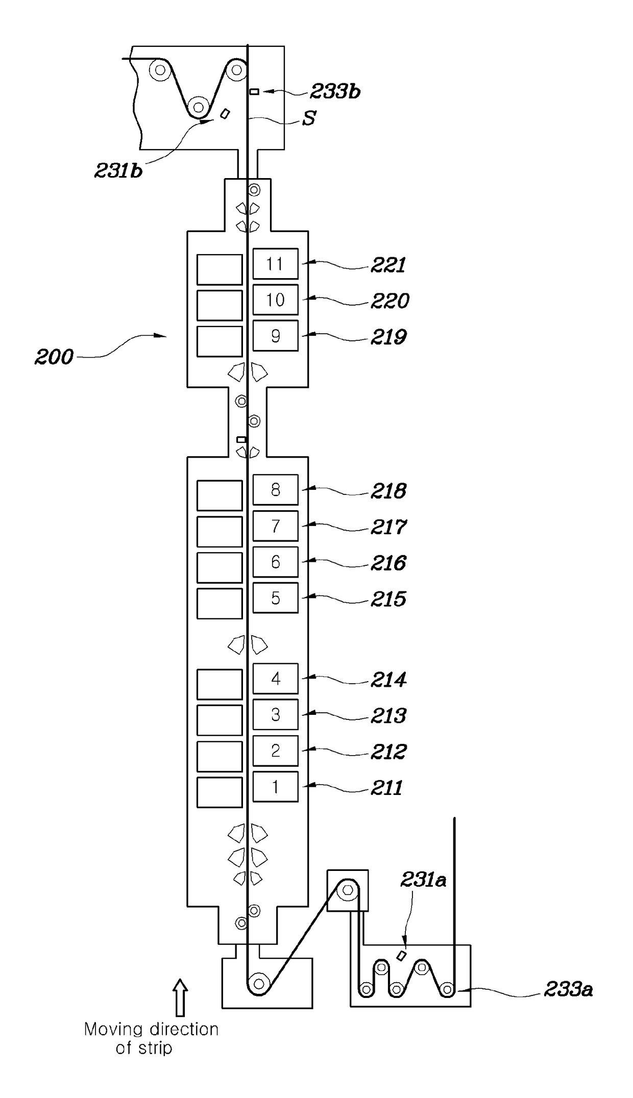
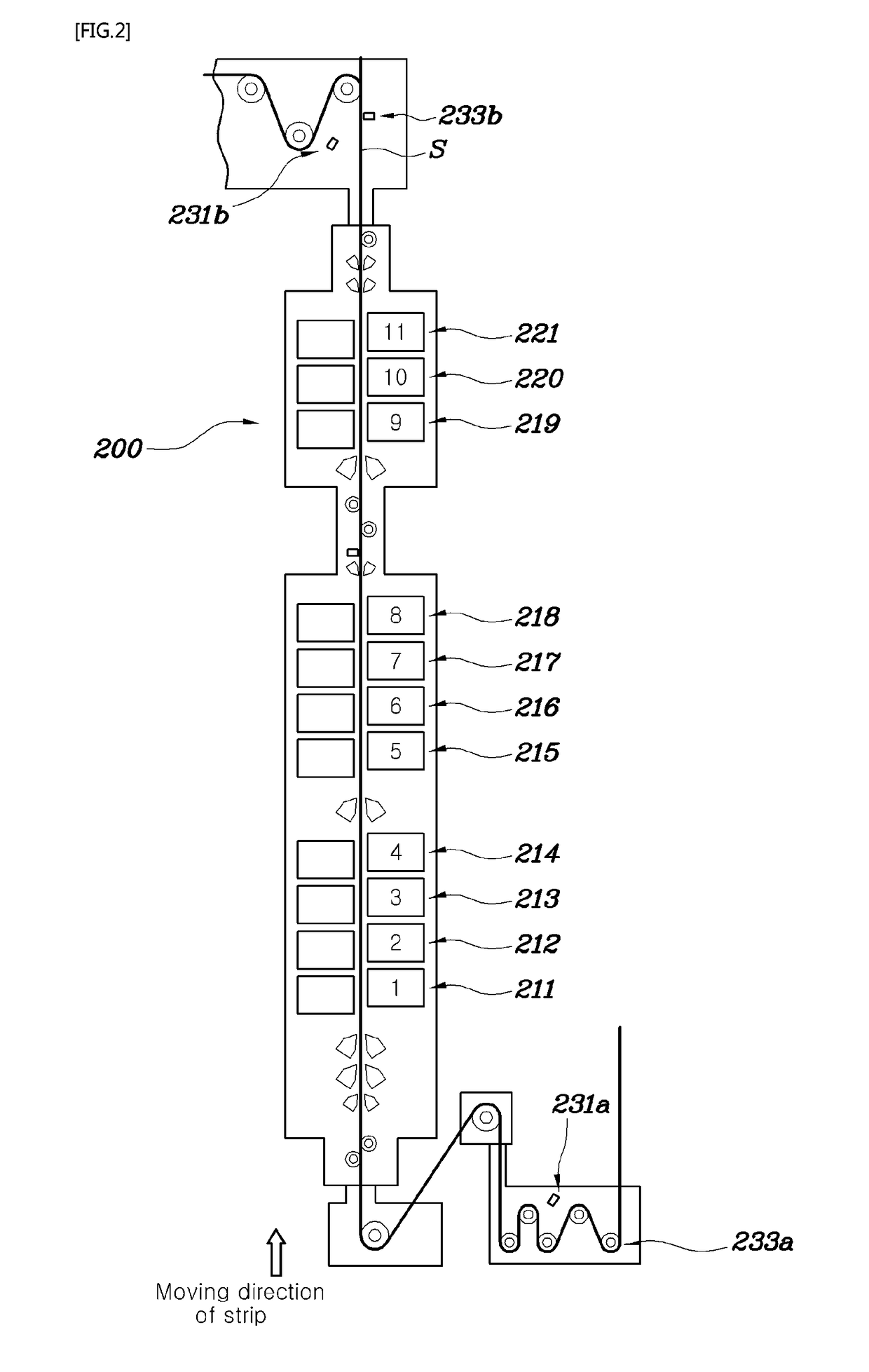
[0031]A method and apparatus for uniformly controlling a strip temperature in a rapid cooling section of a continuous annealing line according to the present invention can measure temperatures using thermometers in an intake end and a discharge end of the rapid cooling section of the continuous annealing line and perform uniform cooling control over the temperature of the strip through flow rate control over spray mist based on feedback / feedforward control technique, thereby minimizing changes in the flatness of the strip.

[0032]First, a description will be given below of an apparatus 100 for uniformly controlling a strip temperature in a rapid cooling section of a continuous annealing line according to the present invention with reference to the drawings.

[0033]the apparatus for uniformly controlling a strip temperature in a rapid cooling se...


PUM

PropertyMeasurementUnit
temperatureaaaaaaaaaa
flow ratesaaaaaaaaaa
flatnessaaaaaaaaaa

Abstract

Provided are a method and apparatus for uniformly controlling the strip temperature of the rapid cooling section of a continuous annealing line. A plurality of sets of cooling nozzle blocks for controlling the strip temperature is installed at the front and back sides of the strip, and is divided into lengthwise flow control nozzle blocks and widthwise flow control nozzle blocks. Strip center temperature meters and widthwise direction temperature meters are installed at the intake and discharge sides of the rapid cooling section. Temperatures obtained using the strip center temperature meters and the width direction temperature meters are used to respectively control the spraying of mist for the lengthwise flow control nozzle blocks and the widthwise flow control nozzle blocks in order to uniformly control the strip temperature and minimize changes in the flatness of the strip. The widthwise temperature meters at the intake and discharge ends of the rapid cooling section of the continuous annealing line are used to detect the temperature. Feedback / feedforward control technique can be used to uniformly control the widthwise temperature of the strip through flow rate control over mist sprayed in the widthwise direction of the rapid cooling section.

Description

CROSS-REFERENCE TO RELATED APPLICATIONS[0001]This application is the United States national phase of International Application No. PCT / KR2012 / 010776 filed Dec. 12, 2012, and claims priority to Korean Patent Application No. 10-2011-0135026 filed Dec. 15, 2011, the disclosures of which are hereby incorporated in their entirety by reference.TECHNICAL FIELD[0002]The present invention relates, in general, to a method and apparatus for uniformly controlling a strip temperature in a rapid cooling section of a continuous annealing line and, more particularly, to a method and apparatus for uniformly controlling a strip temperature in a rapid cooling section of a continuous annealing line, in which widthwise temperatures of the strip are measured in intake and discharge ends of the rapid cooling section of the continuous annealing line, and widthwise flow rate control over mist is carried out using a feedback / feedforward control technique, whereby the widthwise temperature of the strip is uni...

Claims


Application Information

Patent Timeline
Patent Type & Authority Patents(United States)
IPC IPC(8): G05D23/00C21D11/00G05D23/19C21D9/52C21D9/573C21D1/667
CPCC21D11/005C21D9/52C21D9/5735G05D23/19C21D9/573C21D1/667C21D1/00
Inventor LEE, GYOO TAEKPARK, JUNG HUN
Owner POHANG IRON & STEEL CO LTD
Why Eureka
Try Eureka