Energy storage module with reduced damage to electrode terminals

a technology of energy storage module and electrode terminal, which is applied in the field of energy storage module, can solve the problems of affecting the efficiency of operation, requiring untightening of the relay bus bar, and requiring laborious whole operation, so as to avoid torque-induced damage, improve operation efficiency, and prevent damage to the electrode terminal

Active Publication Date: 2017-10-10
HONDA MOTOR CO LTD
View PDF10 Cites 0 Cited by
  • Summary
  • Abstract
  • Description
  • Claims
  • Application Information

AI Technical Summary

Benefits of technology

[0013]The present invention solves the problems of this type, and an object of the present invention is to provide an energy storage module which makes it possible to simplify and improve the efficiency of the operations as a whole, and reduce and / or eliminate damage of electrode terminals as much as possible.
[0015]In the present invention, the terminal frame electrically connecting the electrode terminal of the energy storage cell and the output line has the line connector connected to the output line. The terminal frame is fixed to the end plate by the plurality of fixing points. In the structure, at the time of fixing the output line to the line connector by tightening a nut, etc., the terminal frame is not rotated, thereby avoiding torque induced damage.
[0016]Thus, even if the terminal frame and the output line are connected after the electrode terminal of the energy storage cell and the terminal frame are connected, damage to the electrode terminal is prevented. Accordingly, it becomes possible to simplify, and improve the efficiency of operation such as maintenance operation as a whole. Further, damage of the electrode terminal can be reduced as much as possible.

Problems solved by technology

Therefore, connecting and removing operations have constraints, and the entire operation is laborious.
Further, at the time of conducting maintenance operations, the relay bus bar needs to be untightened.
Accordingly, maintenance operations cannot be performed efficiently.

Method used


Image

  • Energy storage module with reduced damage to electrode terminals
  • Energy storage module with reduced damage to electrode terminals
  • Energy storage module with reduced damage to electrode terminals

Examples


Embodiment Construction

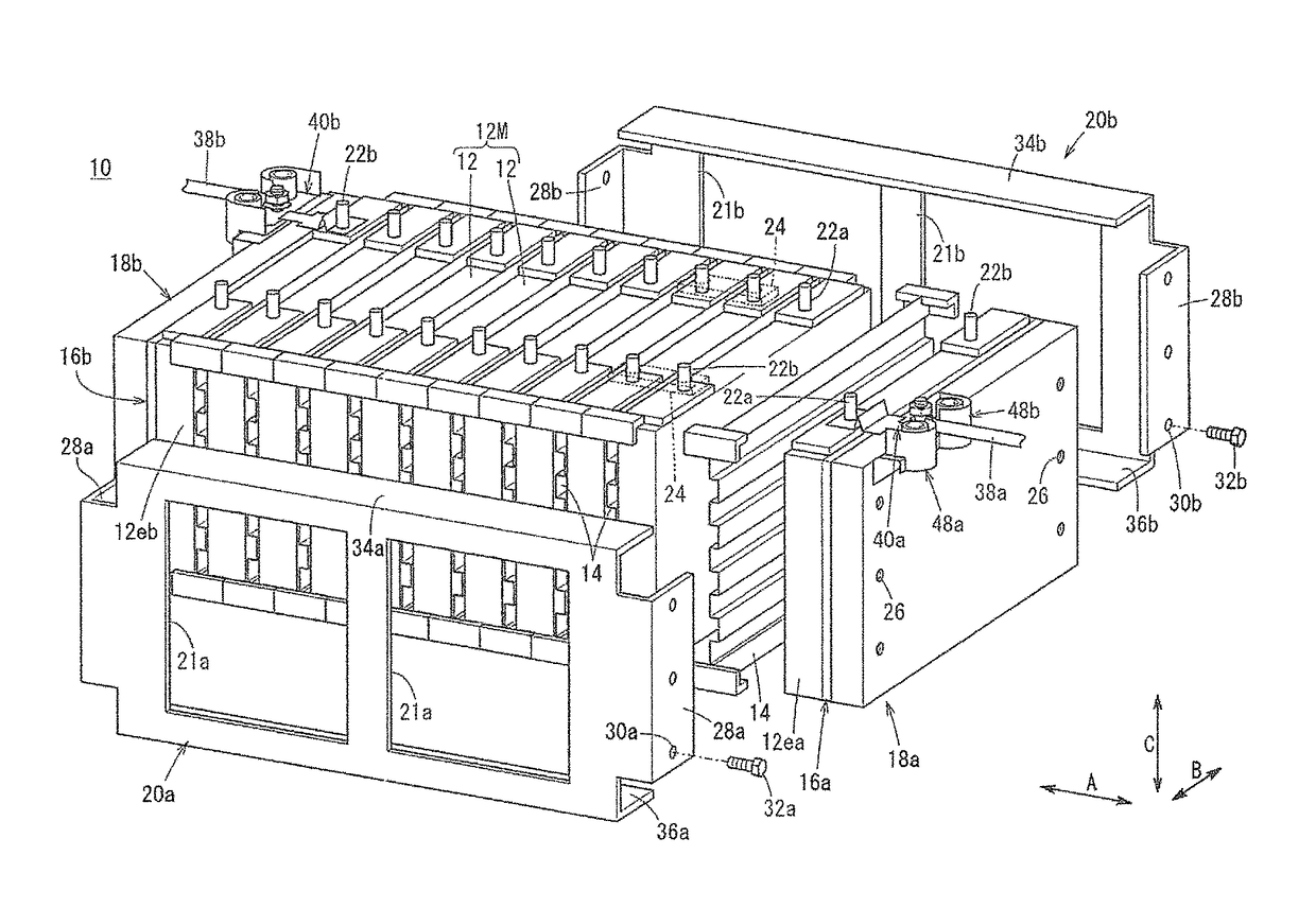
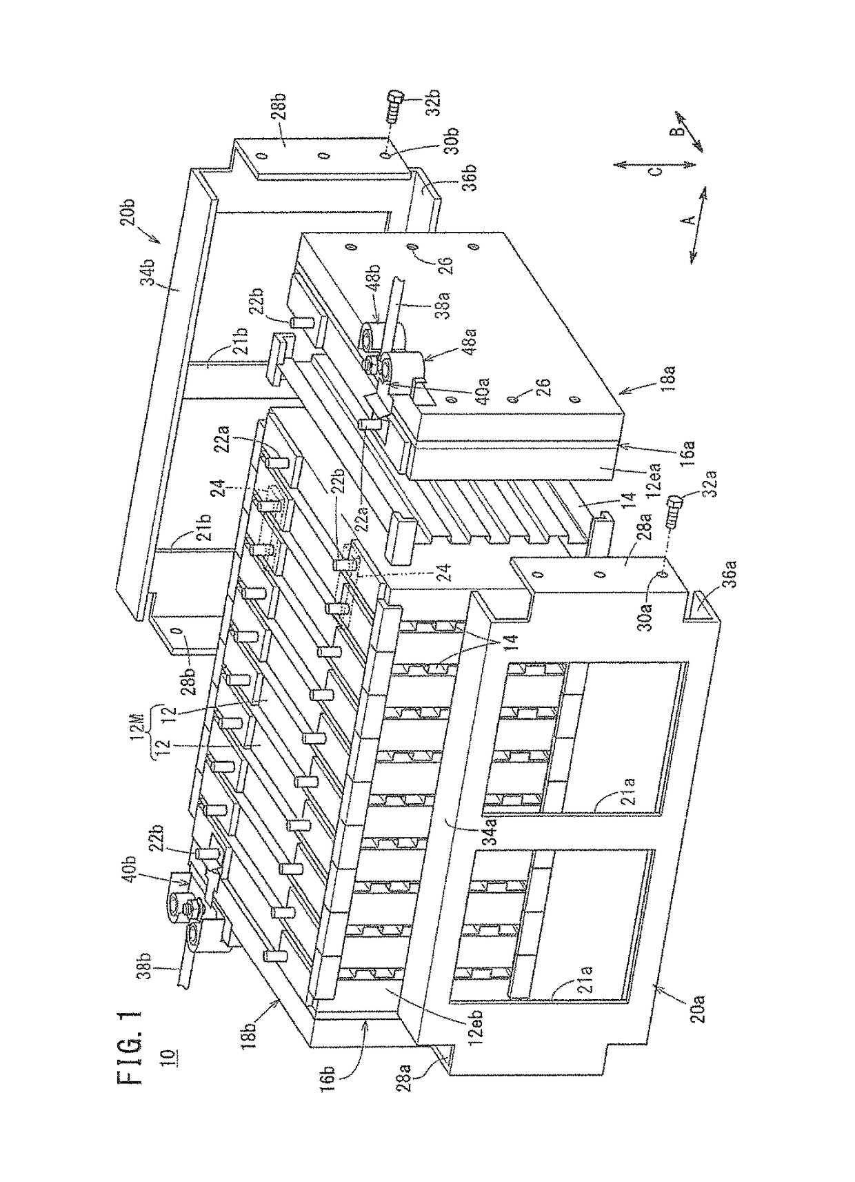
[0030]FIG. 1 illustrates an energy storage module 10 according to a first embodiment of the present invention.

[0031]The energy storage module 10 includes an energy storage cell group 12M formed by stacking a plurality of energy storage cells 12 in a horizontal direction indicted by an arrow A. Each of the energy storage cells 12 has a rectangular shape. The energy storage cells 12 are placed upright, and in this state, the energy storage cells 12 and insulating separators (holders) 14 are stacked together alternately in the direction indicated by the arrow A. The separators 14 can have a corrugated shape in a side view.

[0032]At both ends of the energy storage cell group 12M in the stacking direction, insulator plates (or separators 14) 16a, 16b having a heat insulating function and an electrically insulating function are provided, and rectangular (or square) end plates 18a, 18b are provided outside the insulator plates 16a, 16b. The end plates 18a, 18b are coupled together, e.g., by...


PUM

PropertyMeasurementUnit
surface fixing pointaaaaaaaaaa
output voltageaaaaaaaaaa
connection resistanceaaaaaaaaaa

Abstract

An energy storage module includes an energy storage cell group containing a plurality of energy storage cells stacked in a stacking direction, and a pair of end plates provided at both ends of the energy storage cell group in the stacking direction. A terminal frame is provided at the end plate in order to electrically connect an electrode terminal of the energy storage cell provided at an end in the stacking direction and an output line. The terminal frame is fixed to the end plate by fixing points.

Description

CROSS-REFERENCE TO RELATED APPLICATION[0001]This application is based upon and claims the benefit of priority from Japanese Patent Application No. 2014-143194 filed on Jul. 11, 2014, the contents of which are incorporated herein by reference.BACKGROUND OF THE INVENTION[0002]Field of the Invention[0003]The present invention relates to an energy storage module including an energy storage cell group formed by stacking a plurality of energy storage cells in a stacking direction and a pair of end plates provided at both ends of the energy storage cell group in the stacking direction to hold the energy storage cells of the energy storage cell group together.[0004]Description of the Related Art[0005]In general, an energy storage module including an energy storage cell group formed by stacking a plurality of energy storage cells is known. For example, this energy storage module is mounted in an electrically driven vehicle such as a hybrid vehicle or EV. To this end, the high output voltage ...

Claims


Application Information

Patent Timeline
Patent Type & Authority Patents(United States)
IPC IPC(8): H01M6/42H01M2/20H01M2/10H01M50/209H01M50/249H01M50/296H01M50/51H01M50/516
CPCH01M2/206H01M2/1077H01M2220/20H01M10/045H01M10/0525H01M50/296H01M50/209H01M50/51H01M50/516H01M50/249Y02E60/10Y02P70/50
Inventor KAWATA, MASAOSAKURAI, ATSUSHIWADA, MAKOTO
Owner HONDA MOTOR CO LTD
Why Eureka
Try Eureka