Energy storage module

Active Publication Date: 2016-01-14
HONDA MOTOR CO LTD
View PDF1 Cites 13 Cited by
  • Summary
  • Abstract
  • Description
  • Claims
  • Application Information

AI Technical Summary

Benefits of technology

[0015]In the present invention, the terminal frame electrically connecting the electrode terminal of the energy storage cell and the output line has the line connector connected to the output line. The terminal frame is fixed to the end plate by the plurality of fixing points. In the structure, at the time of fixing the output line to the line connector by tightening a nut, etc., the terminal frame is not rotated, thereby avoiding tor

Problems solved by technology

Therefore, connecting and removing operations have constraints, and the entire operation is laborious.
Further, at the time of conductin

Method used


Image

  • Energy storage module
  • Energy storage module
  • Energy storage module

Examples


Embodiment Construction

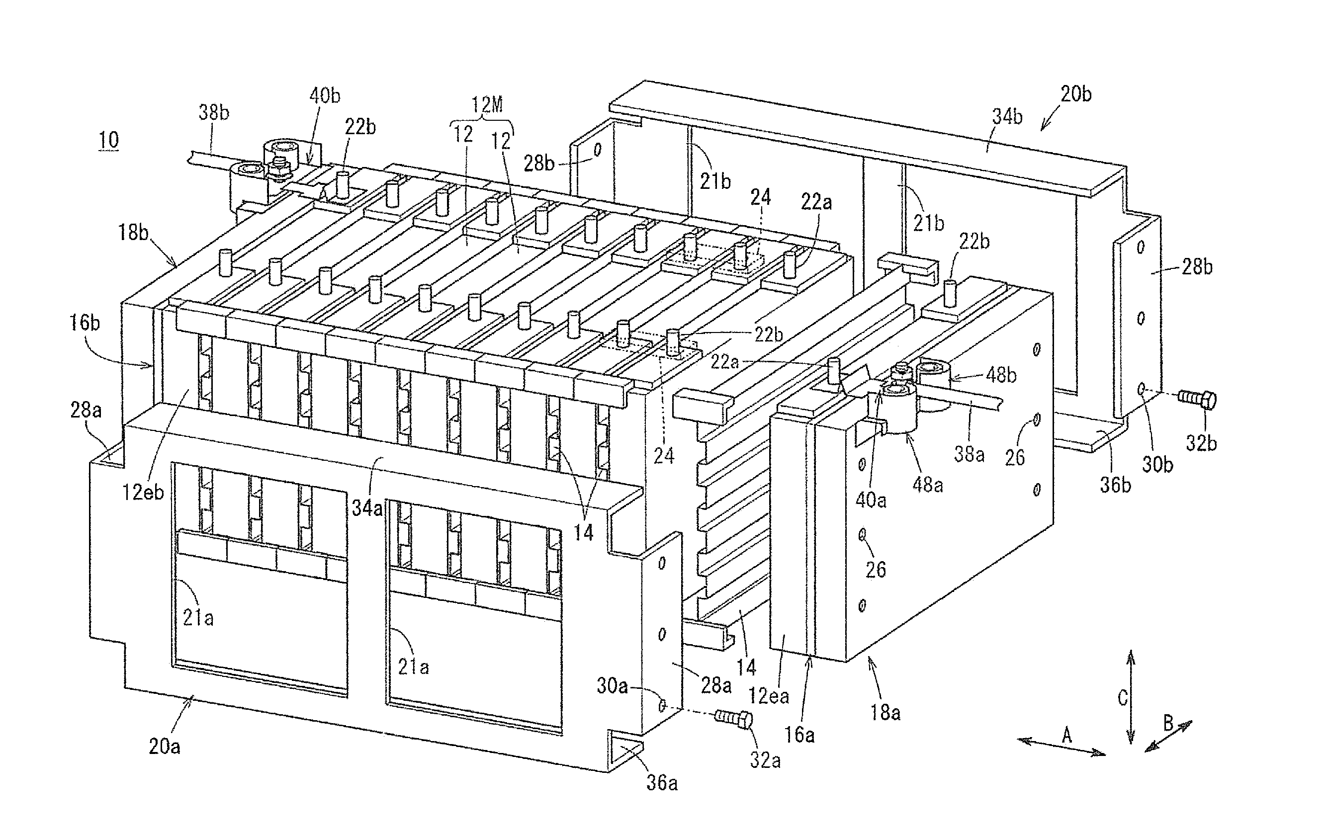
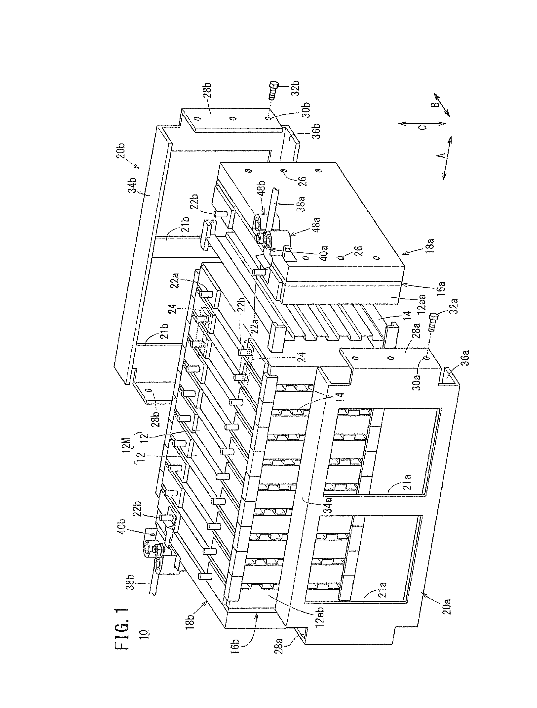
[0030]FIG. 1 illustrates an energy storage module 10 according to a first embodiment of the present invention.

[0031]The energy storage module 10 includes an energy storage cell group 12M formed by stacking a plurality of energy storage cells 12 in a horizontal direction indicted by an arrow A. Each of the energy storage cells 12 has a rectangular shape. The energy storage cells 12 are placed upright, and in this state, the energy storage cells 12 and insulating separators (holders) 14 are stacked together alternately in the direction indicated by the arrow A. The separators 14 can have a corrugated shape in a side view.

[0032]At both ends of the energy storage cell group 12M in the stacking direction, insulator plates (or separators 14) 16a, 16b having a heat insulating function and an electrically insulating function are provided, and rectangular (or square) end plates 18a, 18b are provided outside the insulator plates 16a, 16b. The end plates 18a, 18b are coupled together, e.g., by...


PUM


Abstract

An energy storage module includes an energy storage cell group containing a plurality of energy storage cells stacked in a stacking direction, and a pair of end plates provided at both ends of the energy storage cell group in the stacking direction. A terminal frame is provided at the end plate in order to electrically connect an electrode terminal of the energy storage cell provided at an end in the stacking direction and an output line. The terminal frame is fixed to the end plate by fixing points.

Description

CROSS-REFERENCE TO RELATED APPLICATION[0001]This application is based upon and claims the benefit of priority from Japanese Patent Application No. 2014-143194 filed on Jul. 11, 2014, the contents of which are incorporated herein by reference.BACKGROUND OF THE INVENTION[0002]1. Field of the Invention[0003]The present invention relates to an energy storage module including an energy storage cell group formed by stacking a plurality of energy storage cells in a stacking direction and a pair of end plates provided at both ends of the energy storage cell group in the stacking direction to hold the energy storage cells of the energy storage cell group together.[0004]2. Description of the Related Art[0005]In general, an energy storage module including an energy storage cell group formed by stacking a plurality of energy storage cells is known. For example, this energy storage module is mounted in an electrically driven vehicle such as a hybrid vehicle or EV. To this end, the high output vo...

Claims


Application Information

Patent Timeline
IPC IPC(8): H01M10/0525H01M50/209H01M50/249H01M50/296H01M50/51H01M50/516
CPCH01M2/206H01M2220/20H01M10/0525H01M2/1077H01M10/045H01M50/296H01M50/209H01M50/51H01M50/516H01M50/249Y02E60/10Y02P70/50
Inventor KAWATA, MASAOSAKURAI, ATSUSHIWADA, MAKOTO
Owner HONDA MOTOR CO LTD
Why Eureka
Try Eureka