Single armed trailer coupler locking device

a single-armed, trailer coupler technology, applied in towing devices, padlocks, building locks, etc., can solve problems such as difficulty in handling, misplaced or lost lock bars, and prone to problems with conventional lock bases

Inactive Publication Date: 2017-10-24
YUAN GUOJI
View PDF32 Cites 4 Cited by
  • Summary
  • Abstract
  • Description
  • Claims
  • Application Information

AI Technical Summary

Benefits of technology

[0009]When the locking device is in a locked condition with a trailer coupler, the ball-shaped member is seated in the socket of the trailer coupler, and the lock bracket is placed over the trailer coupler. After the lock bracket being pressed down, the lock bracket has a snugly fit over a section on the top of the trailer coupler. The section is preferably between the vertex of the coupler socket and the coupler's locking latch assembly. This snugly fit and the offset behind the vertex of the coupler socket provide a strong mechanism against a brutal force from turning the single-armed lock bracket in a potential attempt of breaking open the locking device. The offset distance may be optimized for maximum security. Grooves on the arm allows a locking component to be engaged with the lock bracket at different height. Furthermore, the grooves and the locking component may be engaged with each other in a way that restricts the lock bracket from swinging.

Problems solved by technology

When the trailer is not towed or not connected to the vehicle, it can be easily hitched up to another ball mount through the trailer's coupler front end and towed away by an unauthorized person.
Therefore, the lock bar may not be coupled to the lock housing when the device is not in use, which raises the issue of the lock bar being misplaced or lost.
A slightly bent lock bar would prevent the arms from being slid through the apertures, which makes handling more difficult.
And more openings and penetrations make the conventional lock base more prone to problems like blocked or rusty interior.
In addition, a conventional lock bar engaged in a lock base limits the models of trailer couplers that can be positioned over the ball-shaped member and secured by the lock bar.
Therefore, a conventional coupler lock may not be used interchangeably on various trailer couplers that bear different cap and / or rim sizes.

Method used


Image

  • Single armed trailer coupler locking device
  • Single armed trailer coupler locking device
  • Single armed trailer coupler locking device

Examples


Embodiment Construction

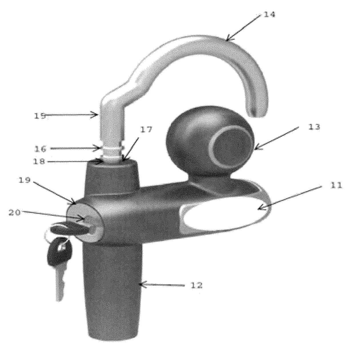
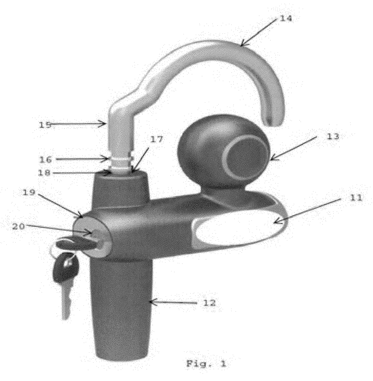
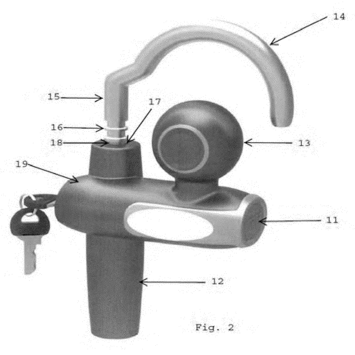
[0023]The locking device of the present invention is designed to be used with a towing coupler. A towing coupler, also known as a trailer coupler, is a device attached to an object being towed. During towing, the towing coupler is matched with a tow hitch installed on a vehicle. The object being towed is commonly referred as a trailer. The object being towed may be but not limited to a travel trailer, a bike trailer, a boat trailer, a single-axle dolly, a multiple-axle dolly, a semi-trailer truck, a popup camper, and a mobile home. When the object is not being towed, the locking device may be applied to the towing coupler in order to obstruct an unauthorized towing.

[0024]Reference is now made in detail to the exemplary embodiments of the invention, examples of which are illustrated in the accompanying drawings. Wherever possible, the same reference numbers will be used throughout the drawings to refer to the same or like parts. The description, embodiments and figures are not to be ...


PUM


Abstract

A locking device for obstructing towing of an unattached trailer has a lock base and a single-armed curved interlock bracket. The lock base has a cylindrical leg. The single-armed interlock bracket has an grooved arm sliding along an aperture on the cylindrical leg and may be permanently attached to the lock base. Grooves on the arm allows a locking means to be engaged with the lock bracket at different height. When engaged, the locking means may restrict the interlock bracket from swirling. The open end of the interlock bracket provides flexibility to accommodate trailer couplers with different cap / rim sizes. The cylindrical leg may have a sealed bottom end and may function as a handle. The locking device may also feature a push-in locking mechanism to lock the interlock bracket in a position without using a key.

Description

CROSS-REFERENCE TO RELATED APPLICATIONS[0001]This application claims priority to Provisional U.S. Patent Application No. 61 / 899,131, filed Nov. 1, 2013, the entirety of which is incorporated by reference herein.FIELD OF INVENTION[0002]The present invention relates to an anti-theft locking device used on a trailer hitch coupler to obstruct towing of an unattached trailer. More particularly, the present invention provides structural improvements over the conventional trailer locking devices.BACKGROUND OF THE INVENTION[0003]Use of trailers towed by various vehicles on the ground or in the water for storing and transporting goods in both domestic and industrial applications is well-known in the field. A typical trailer application may include a hitch mounted on a vehicle with a receiver for receiving a ball mount assembly and a coupler on a trailer with a socket for linking the trailer to the hitch through the ball mount assembly. When the trailer is not towed or not connected to the ve...

Claims


Application Information

Patent Timeline
Patent Type & Authority Patents(United States)
IPC IPC(8): B60D1/60E05B67/36B60D1/06
CPCB60D1/60E05B67/36B60D1/06Y10T70/5854
Inventor YUAN, GUOJI
Owner YUAN GUOJI
Why Eureka
Try Eureka