Bending tester for network optical fiber cable

A technology of bending testing machine and optical fiber line, which is applied in the field of optical fiber line for network, can solve the problems of inflexible adjustment of the bending range of the test piece and inflexible adjustment of the fixed position of the test piece, and achieve a compact structure, improved work efficiency, and simple operation Effect

Active Publication Date: 2016-08-17
上海朋邦实业有限公司
View PDF8 Cites 3 Cited by
  • Summary
  • Abstract
  • Description
  • Claims
  • Application Information

AI Technical Summary

Problems solved by technology

However, this invention has the disadvantages that the adjustment of the bending range of the t

Method used


Image

  • Bending tester for network optical fiber cable
  • Bending tester for network optical fiber cable
  • Bending tester for network optical fiber cable

Examples


Example Embodiment

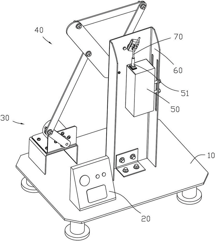
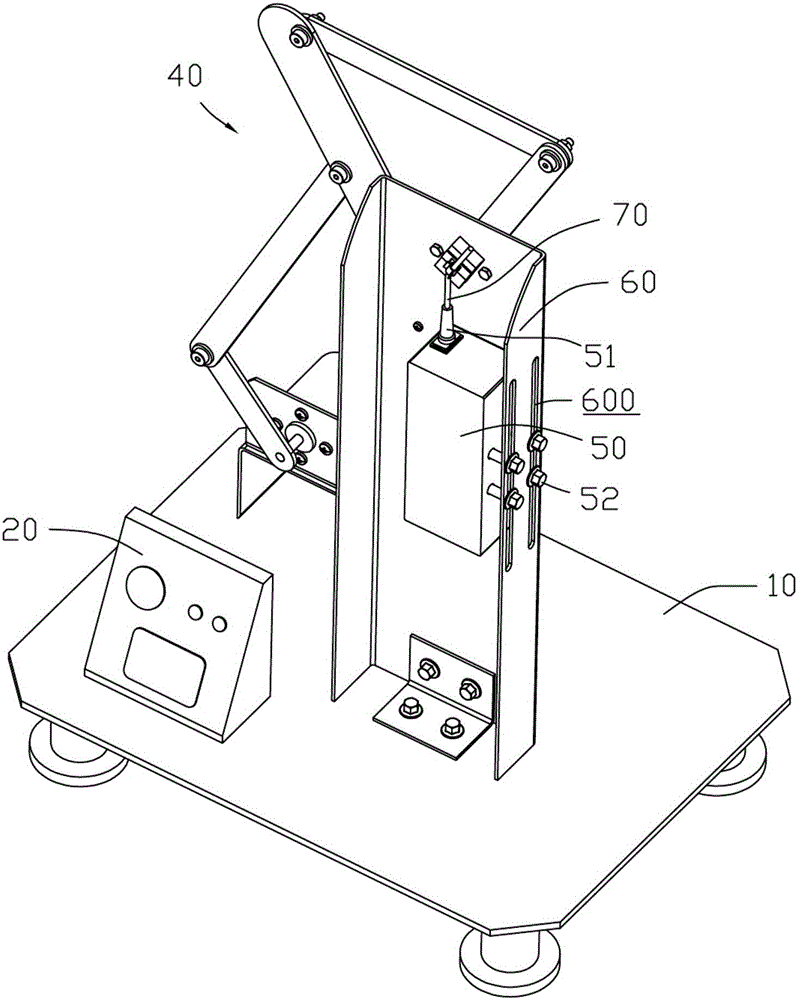
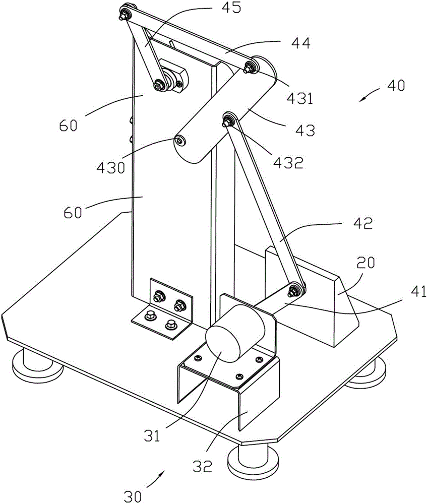
[0015] to combine Figure 1 to Figure 5 , a bending testing machine for network optical fiber lines, including a base 10, a control board 20, a motor assembly 30, a connecting rod assembly 40, a clamp 50 and a clamp seat 60; the base 10 is located at the bottom of the testing machine, and the motor assembly 30 includes The motor 31 and the motor seat 32, the connecting rod assembly 40 includes five connecting rods and an optical fiber clamping plate 47, wherein the first connecting rod 41 is connected to the motor 31, and the optical fiber 70 is installed in the optical fiber clamping plate 47, so The bottom of the fiber optic cable 70 is installed on the clamp 50 , and the clamp 50 is fixed on the clamp seat 60 .

[0016] to combine image 3 and Figure 5 , the connecting rod assembly 40 includes a first connecting rod 41, a second connecting rod 42, a third connecting rod 43, a fourth connecting rod 44, a fifth connecting rod 45, a connecting rod fixing block 46 and an opt...


PUM


Abstract

The invention discloses a bending tester for a network optical fiber cable. The bending tester comprises a base, a control panel, a motor assembly, a connecting rod assembly, a fixture and a fixture seat. The base is located at the bottommost of the tester. The motor assembly comprises a motor and a motor seat. The connecting rod assembly comprises five connecting rods and an optical fiber cable clamping plate, wherein the first connecting rod is connected with the motor, the optical fiber cable is installed in the optical fiber cable clamping plate, the bottom of the optical fiber cable is installed on the fixture, and the fixture is fixed to the fixture seat. The bending tester is compact in structure, easy to operate, and capable of effectively controlling the swing amplitude of the connecting rod assembly, the fixing height of the optical fiber cable can be flexibly adjusted, and thus the working efficiency can be greatly improved.

Description

Technical field: [0001] The invention relates to the technical field of optical fiber cables for networks, in particular to a bending tester for network optical fiber cables. Background technique: [0002] When testing the quality of optical fiber cables for networks, it is necessary to test their voltage, resistance, bending resistance, ampacity and insulation. Among them, bending resistance is a very important link, and the application number is CN201520176823.X. The copper wire swing bending test mechanism includes a base plate, a column installed on the base plate and a speed-regulating motor. The column is equipped with a rotating panel, main transmission gear, sprocket and counting sensor. The rotating panel is equipped with a positioning rod, a tensioning device and The first fixed rod, the clamp guide rail is installed horizontally on the front of the column, and two clamp blocks that can slide back and forth along the clamp guide rail are installed on the clamp guid...

Claims


Application Information

Patent Timeline
IPC IPC(8): G01N3/38
CPCG01N3/38
Inventor 陈永林
Owner 上海朋邦实业有限公司
Why Eureka
Try Eureka