
Auto-positioning structure for upper cover of network plug

a technology of network plugs and structures, applied in the direction of electrical equipment, two-part coupling devices, coupling device connections, etc., can solve the problems of inconvenient and time-consuming, plugging or unplugging the network plugs,

Active Publication Date: 2017-10-24
JYH ENG TECH
View PDF7 Cites 10 Cited by
  • Summary
  • Abstract
  • Description
  • Claims
  • Application Information

AI Technical Summary

Benefits of technology

The invention is an auto-positioning structure for the upper cover of a network plug. This makes it easier to plug or unplug the plug in narrow spaces and makes assembly of core wires more convenient.

Problems solved by technology

It is thus inconvenient and takes much time.
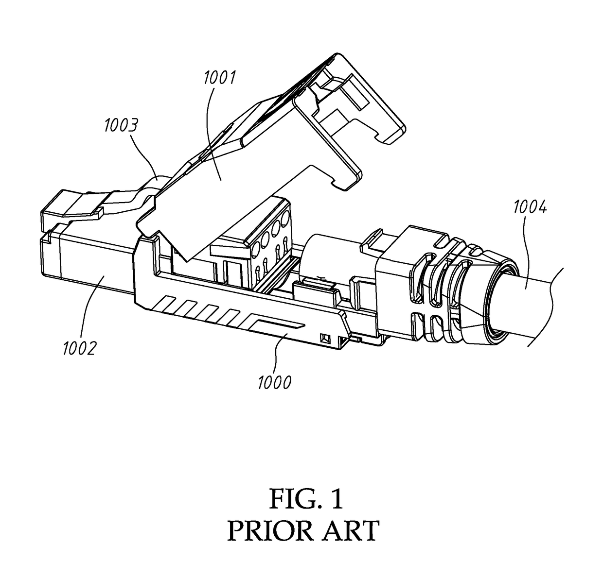
On the other hand, the network plug is often used in a device having a crowded layout, and pressing the tilted spring sheet 1003 often causes a problem of plugging or unplugging the network plug in such a narrow space.

Method used


Image

  • Auto-positioning structure for upper cover of network plug
  • Auto-positioning structure for upper cover of network plug
  • Auto-positioning structure for upper cover of network plug

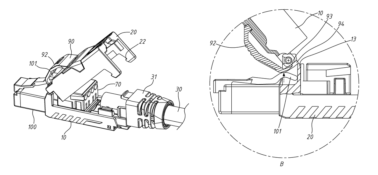
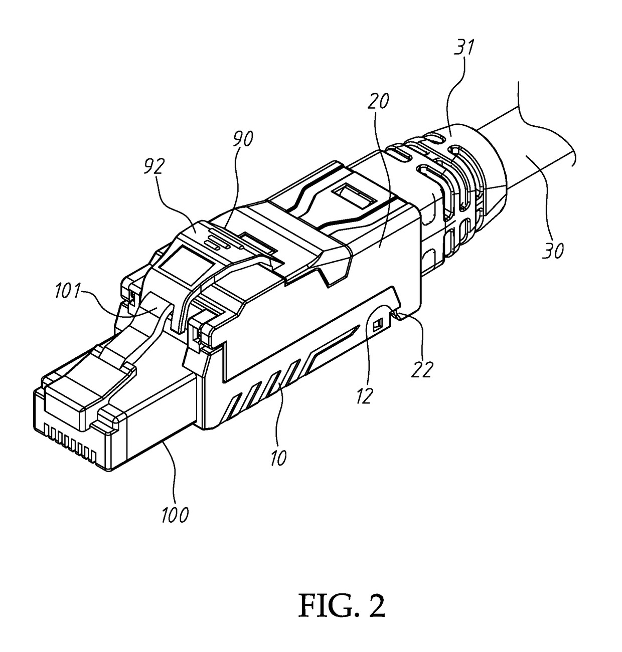
Examples


Embodiment Construction

[0026]The following description is of the best-contemplated mode of carrying out the invention. This description is made for the purpose of illustrating the general principles of the invention and should not be taken in a limiting sense. The scope of the invention is best determined by reference to the appended claims.

[0027]Referring to FIGS. 2 to 5, a network plug of the invention includes a base 10 and an upper cover 20 having an end pivoted to an upper end of the base 10. The upper cover 20 and the base 10 form a main body of the network plug. A network cable 30 extends through a jacket 31, and a front portion of the network cable 30 is inserted into the main body. A base plate 40 is mounted to an inner surface of the base 10, and a circuit board (PCB) 50 is positioned on the base plate 40. A piercing terminal seat 60 is disposed on the circuit board 50, and a press plate 70 is disposed above the piercing terminal seat 60. A lead seat 80 is mounted to a rear end of the base 10 to...


PUM


Abstract

An auto-positioning structure for an upper cover of a network plug includes a base having an upper end and a rear end and an upper cover having an end pivoted to the upper end and assembled with the base to form a main body. A front portion of a network cable is inserted into the main body. A circuit board cooperates with a piercing terminal seat and a press plate to assemble with the network cable. A releasing spring sheet is disposed on the upper cover, and a front base is disposed on the base and corresponding to the releasing spring sheet. An unlock spring sheet is disposed on the front base and facing the releasing spring sheet, wherein the releasing spring sheet pushes the unlock spring sheet when the upper cover is lifted, and the upper cover is positioned when it reaches a predetermined angle.

Description

BACKGROUND OF THE INVENTION[0001]Field of the Invention[0002]The invention relates to an auto-positioning structure for an upper cover of a network plug for automatically positioning the upper cover during a core wire assembly process and facilitating plug or unplug of the network plug.[0003]Description of the Related Art[0004]A network cable usually includes eight core wires internally. The network cable is configured to extend through a jacket to enter a network plug. The core wires are peeled and electrically connected to piercing terminals in the network plug. The network plug can be inserted into a network socket. Each piercing terminal contacts a corresponding terminal in the socket for transmitting signals through the core wires. Every two core wires of the eight core wires are twisted together to form four pairs of twisted core wires.[0005]The mentioned network cable is assembled to a network plug as shown in FIG. 1. The network plug includes a base 1000 and an upper cover 1...

Claims


Application Information

Patent Timeline
Patent Type & Authority Patents(United States)
IPC IPC(8): H01R13/506H01R24/64H01R13/627H01R107/00
CPCH01R13/506H01R24/64H01R13/6272H01R2107/00H01R4/2433H01R4/2429H01R13/6473
Inventor LIN, YEN-LIN
Owner JYH ENG TECH
Learn More