Emissive surfaces and workspaces method and apparatus

a technology of emissive surfaces and workspaces, applied in the field of large electronic information presentation surfaces, can solve the problems of limited ability to simultaneously share content from multiple sources, no way for the single user to accomplish this task, and scape does not enable direct resizing of content on common display screens, so as to improve the overall system

Active Publication Date: 2017-10-31
STEELCASE INC
View PDF78 Cites 24 Cited by
  • Summary
  • Abstract
  • Description
  • Claims
  • Application Information

AI Technical Summary

Benefits of technology

[0019]Where a second user uses a second interface at a different location in the conference space, the second interface would enable directional replication to the different presentation spaces, albeit where the directional replication is different and is based on the relative juxtaposition of the second interface to the presentation spaces. For instance, where the second interface faces the second display screen and away from the first displays screen, replication on the second and first screens may be facilitated via forward and rearward swiping action, in at least some embodiments.

Problems solved by technology

First, the ability to simultaneously share content from multiple sources is limited by the number of common display screens included in the system.
For instance, if first through fourth different sources are used to simultaneously drive first through fourth different Media:scape screens and a user wants to swap content from the fourth screen with content from the first screen, in most cases there is no way for the single user to accomplish this task.
Fourth, Media:scape does not enable direct resizing of content on common display screens to render content in sizes that are optimized for specific viewing applications.
If conferees are spaced from the Media:scape table, the size of content shared on the common screens is often too small to be optimal.
First, known systems includes stationary hardware that restricts how the system can be used by conferees.
Here, for persons to view the common content, in many cases, the arrangement requires users to turn away from each other and toward the common content so that face to face conversations are difficult to carry on.
Second, while session content for several session images may be simultaneously presented via the relatively small presentation spaces provided on the three display screens mounted to the front wall, the content is often too small for actual reference and the content needs to be increased in size in order to appreciate any detail presented.
Increasing content size of some content causes the enlarged content to disadvantageously block out views of other content.
Third, known systems require users to use either a special device like a wand or a portable personal user device to interact with presented content.
To this end, most systems only include a single wand and therefore wand control and content control using the wand has to be passed from one conferee to another which makes egalitarian control less attractive.
While personal user device interfaces are useful, in many cases users may not want to carry a personal device around or the size of the personal device screen may be insufficient to support at least certain useful interface activities.
Fourth, as more features are added to common display screens within a system, portable personal interface devices can become much more complex and far less intuitive to operate.
On a small portable device screen too much information or too many icons or fields can be intimidating.
In addition, where an interface is oriented differently than commonly presented information, the relative juxtaposition of the interface and commonly displayed information can be disorienting.

Method used


Image

  • Emissive surfaces and workspaces method and apparatus
  • Emissive surfaces and workspaces method and apparatus
  • Emissive surfaces and workspaces method and apparatus

Examples


Embodiment Construction

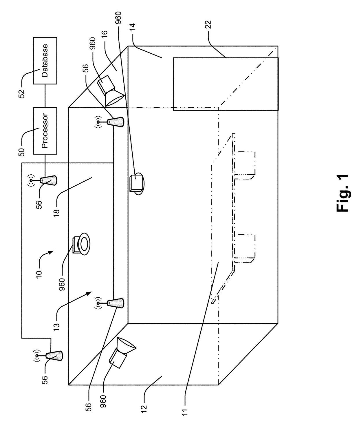
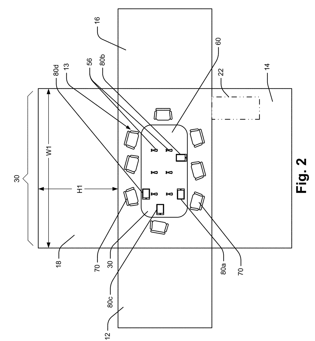
[0103]Referring now to the drawings wherein like reference numerals correspond to similar elements throughout the several views and, more specifically, referring to FIG. 1, the present invention will be described in the context of an exemplary conference space configuration 10 that includes a conference table 11, four wall subassemblies (referred to also hereafter as walls) 12, 14, 16, 18, a processor 50, a database 52 and a plurality of wireless access points 56. The walls 12, 14, 16 and 18 form a rectangular space and include first and second end walls 12 and 16 and first and second side walls 14 and 18. A door or egress 22 for entering and exiting the space 10 is located in wall 14 adjacent wall 16. In the interest of simplifying this explanation, the walls 12, 14, 16 and 18 will be referred to as east, south, west and north walls, respectively. In FIG. 2 and other figures thereafter having a similar appearance, the walls 12, 14, 16 and 18 and table 11 are shown in a top plan vie...


PUM


Abstract

A conferencing arrangement and method for sharing information within a conference space, the arrangement comprising a common presentation surface positioned within the conference space, the common presentation surface including a presentation surface area, a common presentation surface driver, a system processor linked to the driver, the system processor receiving information content and presenting the information content via the common presentation surface and a user interface device including a device display screen and a device processor, the device processor programmed to provide a dynamic interface via the device display screen that is usable to create an arbitrary number of distinct sharing spaces on the presentation surface area for sharing information content and to automatically modify the interface to include features for controlling content presented in the sharing spaces as the number of distinct sharing spaces is altered.

Description

CROSS-REFERENCE TO RELATED APPLICATIONS[0001]This application is a continuation in-part of U.S. patent application Ser. No. 14 / 159,589 which was filed on Jan. 21, 2014 which is titled “Emissive Shapes And Control Systems” and also claims priority there through to U.S. provisional patent application No. 61 / 756,753 which was filed on Jan. 25, 2013 which is titled “Emissive Shapes And Control Systems” and claims priority to provisional U.S. patent application No. 61 / 886,235 which was filed on Oct. 3, 2013 which is titled “Emissive Surfaces And Workspaces Method And Apparatus” as well as to U.S. provisional patent application No. 61 / 911,013 which was filed on Dec. 3, 2013 which is titled “Curved Display And Curved Display Support”, each of which is incorporated herein in its entirety be reference.STATEMENT REGARDING FEDERALLY SPONSORED RESEARCH OR DEVELOPMENT[0002]Not applicable.BACKGROUND OF THE INVENTION[0003]The present invention relates to large electronic information presentation s...

Claims


Application Information

Patent Timeline
Patent Type & Authority Patents(United States)
IPC IPC(8): H04N7/15G06F3/0484G06F3/0481G06F3/0488H04L12/18
CPCG06F3/0481G06F3/04847G06F3/0488H04L12/1813A47B21/00G06F1/16A47B2021/0076A47B2200/0073A47B2200/0071A47B83/001A47B21/007A47B2083/006G06Q10/06311H04L63/102G06V40/70H04L67/535
Inventor BALOGA, MARK A
Owner STEELCASE INC
Why Eureka
Try Eureka