
Pressure regulator adaptable to compressed gas cartridge

a technology of pressure regulator and compressed gas cartridge, which is applied in the direction of fluid pressure control, container discharge methods, instruments, etc., can solve the problems that would not have worked at the source, and achieve the effect of low manufacturing cost and high reliability

Active Publication Date: 2008-02-26
HOLLARS ANTHONY SCOTT
View PDF12 Cites 87 Cited by
  • Summary
  • Abstract
  • Description
  • Claims
  • Application Information

AI Technical Summary

Benefits of technology

[0015]The benefits in this design allow source pressures to be rather low or extremely high. Typically, the flow-obstructing component of this assembly is a rigid ball or substantially circular disk. The rigid seat allows only the obstructing component of the valve to compress the elastomeric seal a pre-determined amount. Any additional forces on the valve obstructing part, such as from a high source pressure, transfer to the rigid valve seat, thus not further compressing the elastomeric seal and damaging it.
[0016]This hybrid valve assembly allows increased versatility over previous designs and has proven to work well in a pressure regulator. One major benefit is that the source pressure can start out high such as occurs when harnessing a compressed gas cartridge, or when a harnessed compressed gas cartridge is subjected to heat where only the traditional hard valve and seat design would reliably retain such source pressures. At a later time, such as when some of the fluid in a compressed gas cartridge has been consumed, the source pressure is lower. A traditional elastomeric sealed inlet valve would appropriately retain the lower pressure but would not have worked when the source pressure was higher. Therefore, a need exists for a valve that can handle extremely high inlet pressures and reliably work as the inlet pressure considerably decreases. In practice, this scenario is typical when harnessing a compressed gas cartridge and desiring a substantially constant outlet pressure regardless of cartridge (source) pressure.
[0017]Additionally, because the rigid valve seat is supporting the flow-obstructing component of the valve, the elastomeric seal is prevented from taking a compression-set and works well as valve assembly temperature varies. This is also resistant to contamination or corrosion allowing long-term reliable containment of high or low pressures providing advantages of both valve prior-art designs without the disadvantages of either.
[0018]The main regulator body is preferably molded from a fiber-reinforced plastic therefore features can easily be reproduced on each unit once the initial molds are built.
[0019]A safety feature that particularly is preferred is negative vents that allow fluid to escape the regulator should the pressure contained by the piston and biased by the regulator main spring become excessive. It is an object of the invention to provide adequate system adjustability so that the regulator can burp off excessive back-pressure.
[0022]The intention of this design is simplicity through fewer parts with perhaps lower manufacturing cost than any existing regulator available today. Additionally, high reliability should be realized from the repeatability standpoint of plastic molded parts. Once the design is proven, each duplicate part should be substantially equal.

Problems solved by technology

A traditional elastomeric sealed inlet valve would appropriately retain the lower pressure but would not have worked when the source pressure was higher.

Method used


Image

  • Pressure regulator adaptable to compressed gas cartridge
  • Pressure regulator adaptable to compressed gas cartridge
  • Pressure regulator adaptable to compressed gas cartridge

Examples


Embodiment Construction

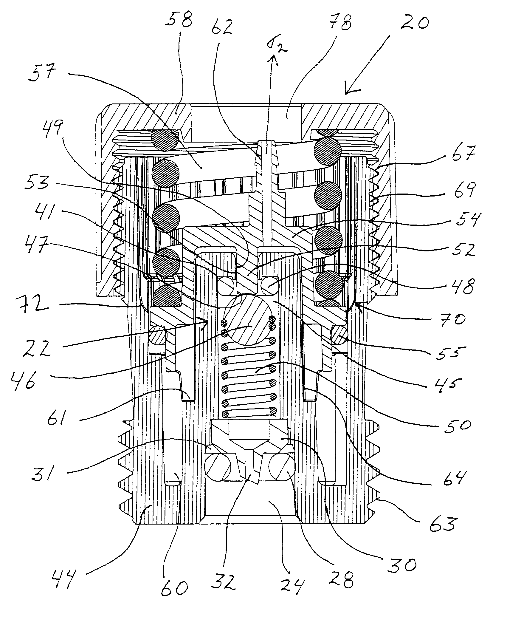
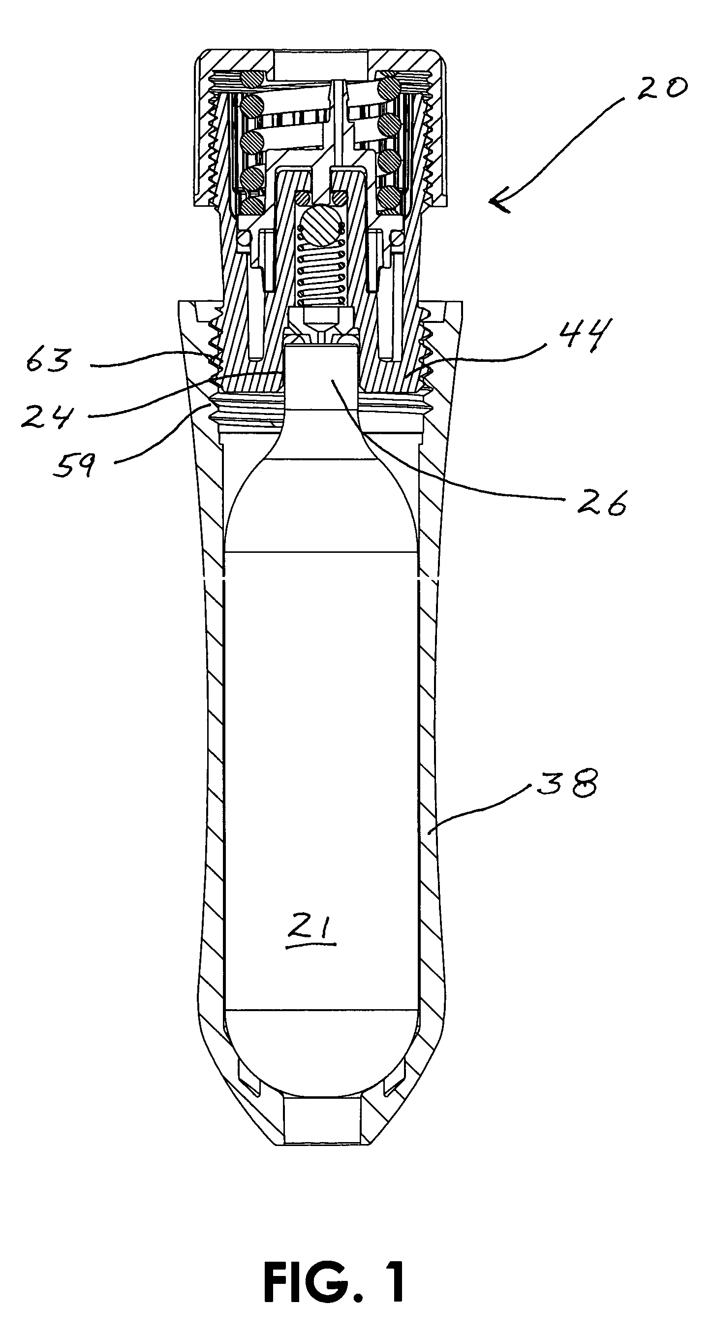
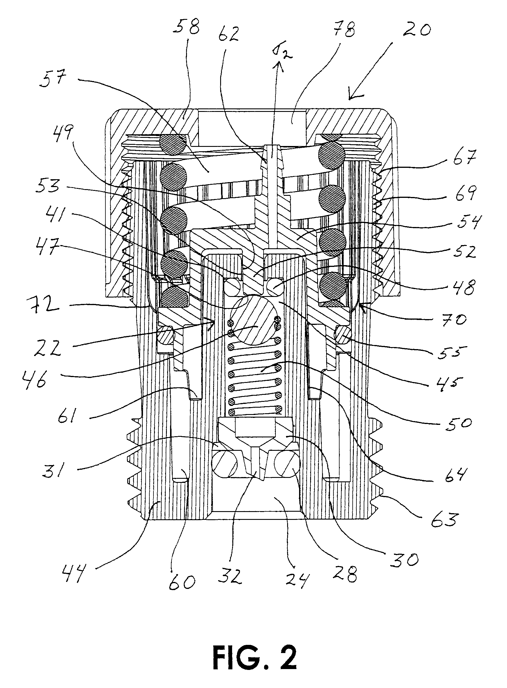
[0030]FIG. 1 illustrates an exemplary embodiment of a pressure regulator 20 of the present invention. Although the present invention is primarily intended to be used with a pressurized cartridge 21 consisting essentially of CO2 gas, other pressurized gases or fluids may be harnessed out of compressed gas cartridges such as nitrogen or oxygen. Pressure regulator 20 generally includes a cartridge-retaining container 38 and a regulator body 44. Cartridge-retaining container 38 and regulator body 44 are preferably molded from a glass-filled nylon or similar material. A female thread 59 on cartridge-retaining container mates with a male thread 63 that is integrally formed as a feature on regulator body 44. Naturally, other materials exhibiting the afore-mentioned characteristics are equally suitable. Compressed gas cartridge 21 comprises a neck 26 that fits into a non-threaded lance housing 24 that is an integral feature of pressure regulator 20.

[0031]FIG. 2 illustrates a cross-section v...


PUM


Abstract

This pressure regulator is specifically designed to operate with a portable compressed gas cartridge thus reducing the high vapor pressure found in compressed gas cartridges down to a substantially consistent outlet pressure. Due to the nature of the crowded regulator art, the soon to be embodied pressure regulator has been specifically embodied for use in the portable compressed gas cartridge harnessing art and this specific use is carried into the claims. Exemplified in the pressure regulator embodiments is a reduced amount of components over existing designs. Additionally, safety and reliability features have been integrated into the design and will shortly be taught in the following paragraphs. A burp-off feature in all embodiments will be exemplified that vents back-pressure spikes as well as a method of adjusting the burp-off back-pressure spikes independent of regulated pressure in some embodiments.

Description

CROSS REFERENCE TO RELATED APPLICATIONS[0001]Provisional patent application No. 60 / 579,763 filed Jun. 16, 2004.FEDERALLY SPONSORED RESEARCH[0002]Not applicable.REFERENCE TO A MICROFICHE APPENDIX[0003]Not applicable.FIELD OF THE INVENTION[0004]This invention relates to a piston-type fluid pressure regulator featuring a novel fluid inlet valve, capable of regulating inlet pressures ranging from low to high. More particularly, the present invention is capable of regulating portable, compressed gas cartridges at high pressure down to a workable, substantially constant outlet pressure. Fewer components over the prior-art are one design emphasis thus making a simplistic and reliable regulator that is both easy and relatively inexpensive to manufacture.BACKGROUND OF THE INVENTION[0005]Pressure regulators have existed for many years and the field is crowded with different designs. Yet, innovative features are still being introduced into pressure regulators such as safety features, compatibi...

Claims


Application Information

Patent Timeline
IPC IPC(8): G05D16/10
CPCF17C13/04G05D16/106F17C2205/0338F17C2201/0109F17C2201/058F17C2205/0111F17C2205/0126F17C2205/032F17C2205/0323F17C2205/0385F17C2209/2109F17C2221/011F17C2221/013F17C2221/014F17C2223/0123F17C2223/035F17C2223/036F17C2270/0718Y10T137/2607Y10T137/7808Y10T137/7825Y10T137/7826
Inventor HOLLARS, ANTHONY SCOTT
Owner HOLLARS ANTHONY SCOTT
Learn More