Axial force measurement method

a technology of axial force and measurement method, which is applied in the direction of force/torque/work measurement apparatus, image analysis, image enhancement, etc., can solve the problem that the displacement amount at both ends cannot be accurately approximated, the end portions obtained by approximation cannot be accurate, and it is not unlikely that the axial force cannot be measured accurately. to achieve the effect of accurately and stably measuring

Active Publication Date: 2017-10-31
TOYOTA JIDOSHA KK
View PDF7 Cites 8 Cited by
  • Summary
  • Abstract
  • Description
  • Claims
  • Application Information

AI Technical Summary

Benefits of technology

[0008]The invention provides an axial force measurement method by which an axial force can be measured accurately and stably.
[0014]The effect demonstrated according to the aspect of the invention is that the axial force can be measured accurately and stably.

Problems solved by technology

However, in this case, it is not unlikely that the measurement results on the displacement amount at both ends cannot be accurately approximated, that is, the end portions obtained by approximation cannot be accurate.
As a result, it is not unlikely that the axial force cannot be measured accurately.

Method used


Image

  • Axial force measurement method
  • Axial force measurement method
  • Axial force measurement method

Examples


first embodiment

[0032]The axial force measurement method will be described below.

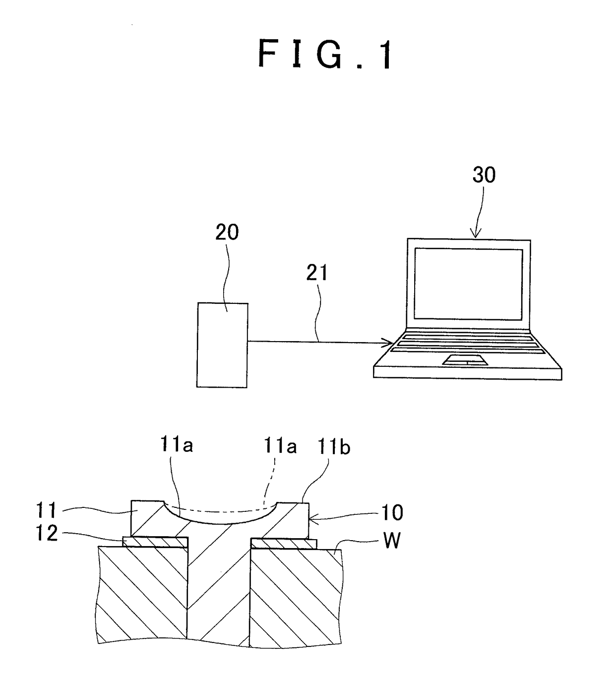
[0033]As depicted in FIG. 1, the axial force measurement method serves to measure the axial force of a bolt 10 fastened to an object to be fastened W.

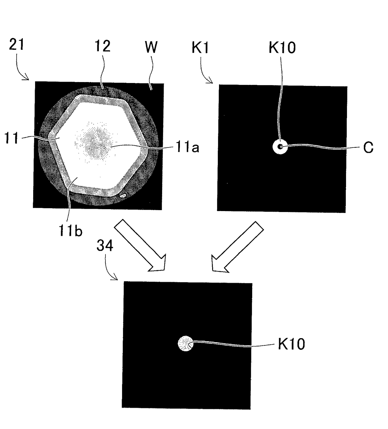
[0034]The bolt 10 of the first embodiment is assumed to be a hexagonal bolt in which a recess 11a is formed in the gravity center (center) of a head 11, and an outer end portion is formed as a flat top portion 11b. Further, in the bolt 10, a flange 12 is formed below the head 11. The recess 11a is positioned lower than the top portion 11b.

[0035]When the bolt 10 is fastened, the recess 11a recedes with centering on the gravity center, and the displacement amount of the head 11 increases as the axial force increases (see the recess 11a in a state before the fastening which is indicated by a two-dot chain line in FIG. 1). In other words, there is a correlation between the axial force and the displacement amount of the head 11 before and after the fastening (see FIG. 13).

[0...

second embodiment

[0129]The axial force measurement method of the second embodiment will be explained below.

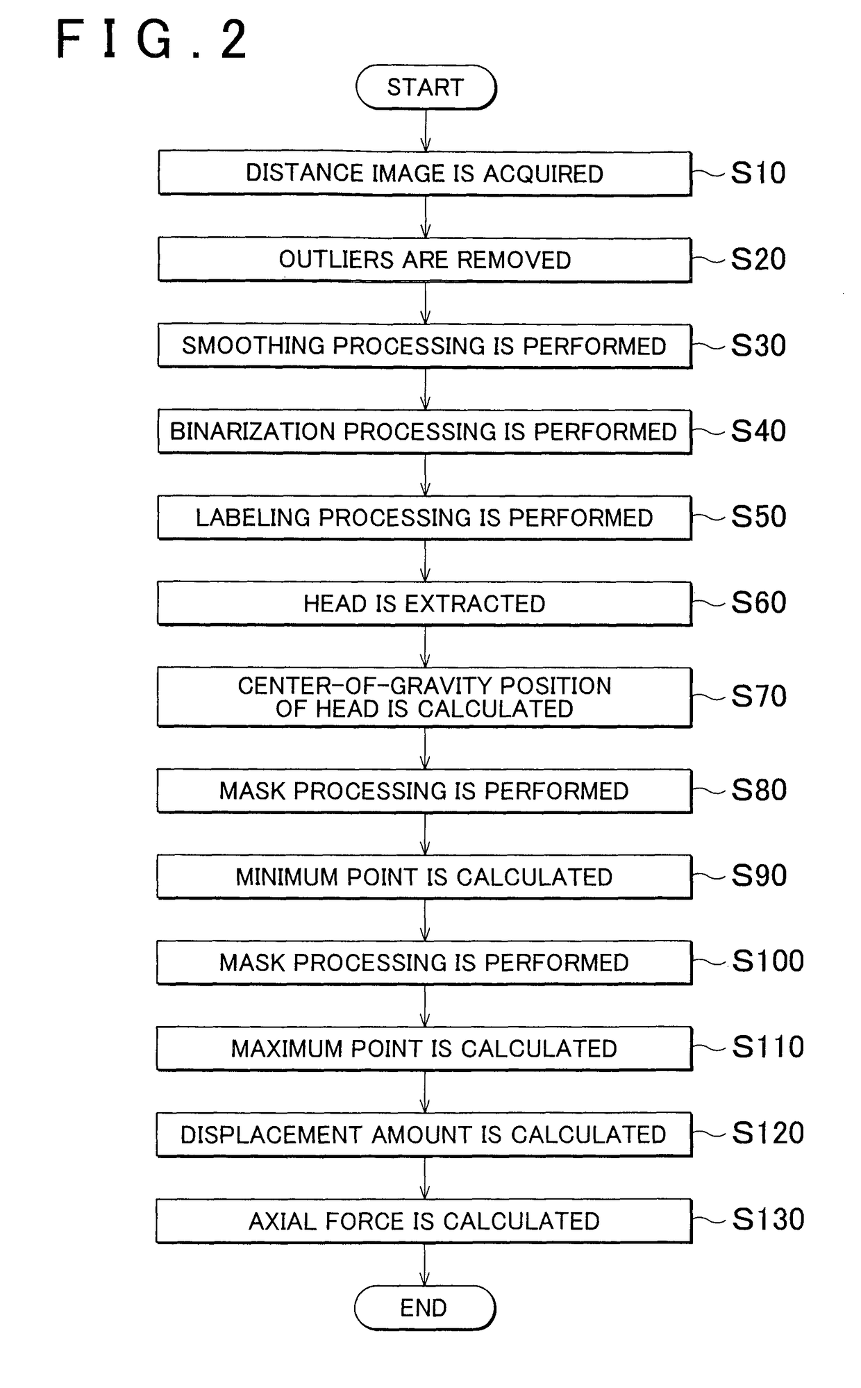
[0130]In the axial force measurement method of the second embodiment, the contents of the mask processing performed during the calculation of the maximum point and the calculation contents of the maximum point are different from those of the axial force measurement method of the first embodiment. Therefore, the step of implementing the mask processing and the step of calculating the maximum point (steps corresponding to steps S100 and S110 of the first embodiment) will be described hereinbelow in detail, and the explanation of other steps will be omitted.

[0131]As depicted in FIG. 16, in the axial force measurement method of the second embodiment, a reference image K3 is created, which includes a first circle K31 which is identical to the first circle K21 of the first embodiment and centered on the gravity center position C of the head 11 of the bolt 10 and a second circle K32 which is less than...


PUM

PropertyMeasurementUnit
axial forceaaaaaaaaaa
axial force measurementaaaaaaaaaa
axial forceaaaaaaaaaa

Abstract

An axial force measurement method includes: a step of calculating an average value of the height of pixels positioned inside a minimum circle, which is centered on a gravity center position of a head, as a minimum point; a step of extracting pixels with a relatively large height from the pixels on the basis of a pixel value of the pixels and calculating an average value of the height of the extracted pixels as a maximum point; a step of calculating a displacement amount of the head on the basis of a difference between the minimum point and the maximum point; and a step of calculating an axial force by substituting the displacement amount of the head into a relational expression of an axial force and the displacement amount of the head.

Description

BACKGROUND OF THE INVENTION[0001]1. Field of the Invention[0002]The invention relates to an axial force measurement method for measuring an axial force of a bolt fastened to an object to be fastened.[0003]2. Description of Related Art[0004]The axial force of a bolt fastened to an object to be fastened is measured to, for example, verify the fastened state of the bolt. There is a correlation between the axial force and the displacement amount of the bolt head (that is, the difference in the recession amount of the head between the states before and after fastening). Therefore, the axial force is typically measured by acquiring the correlation between the axial force and the displacement amount of the head in advance, measuring the displacement amount of the head when actually measuring the axial force, and then measuring the axial force on the basis of the correlation.[0005]In “A Measurement Method of Bolt Loads Based on Deformation of a Top Surface of a Bolt Head”, Transactions of t...

Claims


Application Information

Patent Timeline
Patent Type & Authority Patents(United States)
IPC IPC(8): G06K9/00G06T7/00G01L5/00G06T7/66
CPCG06T7/0006G06T7/66G01L5/0038G06T2207/30164
Inventor NAKAMURA, HISANORISAKAKIBARA, MASAHITOMORI, TATSUROHIRANO, YUICHIMATSUMOTO, YUSUKESAKUI, TAKASHI
Owner TOYOTA JIDOSHA KK
Why Eureka
Try Eureka