Cutting apparatus

a technology of cutting apparatus and cutting blade, which is applied in the direction of manufacturing tools, grinding machine components, metal-working machine components, etc., can solve the problems of difficult to set a threshold value to be compared with the output value, the condition of the cutting blade, and the variation in the output value of the vibration signal generated from the vibration signal generation, etc., to achieve accurate and stable determination

Active Publication Date: 2018-10-25
DISCO CORP
View PDF7 Cites 6 Cited by
  • Summary
  • Abstract
  • Description
  • Claims
  • Application Information

AI Technical Summary

Benefits of technology

[0005]It is therefore an object of the present invention to provide a cutting apparatus which can stably determine whether or not the processing circumstances are good.
[0007]With this configuration, the processing elastic wave data detected in actually processing the workpiece is divided by the ratio calculated by the ratio calculating section to thereby obtain a corrected value. Then, this corrected value is compared with the threshold value to determine whether or not the actual processing is abnormal. Accordingly, a change in value detected by the elastic wave detecting sensor due to a difference in condition of the cutting blade can be corrected by using the ratio between the reference idling elastic wave data and the actual idling elastic wave data. Then, the corrected value for the processing elastic wave data can be compared with the threshold value. Accordingly, whether or not the processing circumstances are good can be determined accurately and stably.

Problems solved by technology

However, the detection method described in Japanese Patent Laid-open No. 2015-170743 has a problem such that a slight difference in condition of the cutting blade such as a difference in cutting edge height may be caused by production error of the cutting blade or wearing of the cutting blade and that this slight difference in condition of the cutting blade may cause variations in output value for the vibration signal generated from the vibration signal generating means.
When such variations in output value are caused, it is difficult to set a threshold value to be compared with the output value in determining the circumstances of processing by the cutting blade.
As a result, whether or not the processing circumstances are good cannot be accurately determined.

Method used


Image

  • Cutting apparatus
  • Cutting apparatus
  • Cutting apparatus

Examples


Embodiment Construction

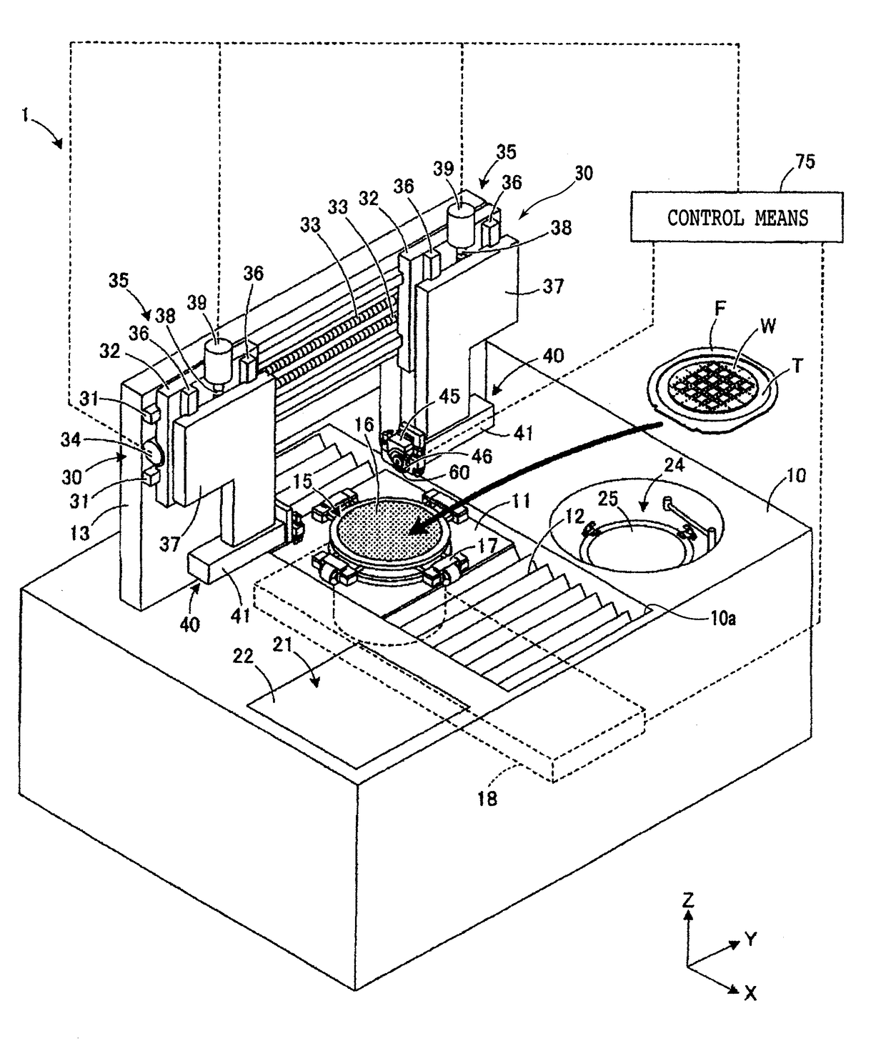
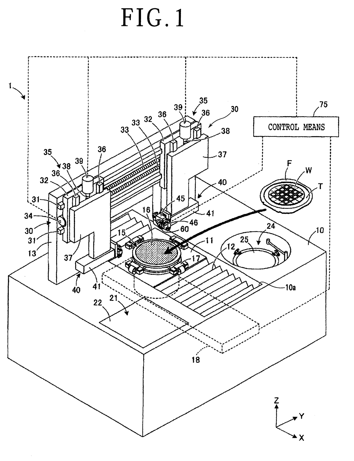
[0019]There will now be described a cutting apparatus 1 according to a preferred embodiment of the present invention with reference to the attached drawings. FIG. 1 is a perspective view of the cutting apparatus 1 according to this preferred embodiment. The cutting apparatus 1 essentially has a structure capable of detecting an elastic wave generated in a cutting blade as in this preferred embodiment, and the configuration of the cutting apparatus 1 is not limited to that shown in FIG. 1.

[0020]As shown in FIG. 1, the cutting apparatus 1 is configured so that a cutting blade 60 and a chuck table 15 are relatively moved to thereby cut a workpiece W held on the chuck table 15 by using the cutting blade 60. The front side of the workpiece W is partitioned into a plurality of separate regions by a plurality of crossing division lines, and a plurality of devices are formed in these respective plural separate regions. The workpiece W is attached to a dicing tape T at a central portion ther...


PUM


Abstract

Disclosed herein is a cutting apparatus having a cutting blade for cutting a workpiece held on a chuck table. The cutting apparatus includes an elastic wave detecting sensor for detecting an elastic wave due to the rotation of the cutting blade, a reference data storing section configured to store reference data as a set of reference processing elastic wave data detected in previously processing the workpiece and reference idling elastic wave data detected in the condition where the cutting blade is idling before processing, a threshold value storing section configured to store a threshold value set on the basis of the reference processing elastic wave data, a ratio calculating section configured to calculate the ratio of idling elastic wave data detected at the time just before actually processing the workpiece to the reference idling elastic wave data, and a determining section configured to divide processing elastic wave data detected during the actual processing by the ratio calculated by the ratio calculating section to thereby obtain a corrected value and then determine that the actual processing is abnormal when the corrected value is greater than the threshold value.

Description

BACKGROUND OF THE INVENTIONField of the Invention[0001]The present invention relates to a cutting apparatus for cutting a workpiece by using a cutting blade.Description of the Related Art[0002]A platelike workpiece typified by a semiconductor wafer is cut by an annular cutting blade included in a cutting apparatus, for example, thereby dividing the workpiece into a plurality of chips. When any abnormality such as chipping of the cutting blade, a reduction in cutting performance, contact of the cutting blade with foreign matter, and a change in processing load occurs during the cutting of the workpiece, the cutting blade may vibrate. As a method of detecting such abnormality of the cutting blade, there has been proposed a method of detecting the chipping of the cutting blade by using an optical sensor (see Japanese Patent No. 4704816, for example) or a method of detecting a processing load by monitoring a current passing through a motor for driving a spindle.[0003]In the method using...

Claims


Application Information

Patent Timeline
Patent Type & Authority Applications(United States)
IPC IPC(8): B23Q17/09B23Q17/12B26D5/00
CPCB23Q17/0971B23Q17/12B26D5/005B24B49/10B23Q2717/00B28D5/0058B28D5/0094B28D5/023H01L21/67
Inventor TSUNO, TAKAHIKOMIYAKAWA, SAKISUGIYAMA, TOMOAKI
Owner DISCO CORP
Why Eureka
Try Eureka