Radar device

Inactive Publication Date: 2006-04-18
FUJITSU LTD
View PDF15 Cites 6 Cited by
  • Summary
  • Abstract
  • Description
  • Claims
  • Application Information

AI Technical Summary

Benefits of technology

[0027]It is an object of the present invention to provide a radar device which can precisely determine

Problems solved by technology

For this reason, it can be highly expected that a serious error occurs in relative distance to the target.
Further, the enlargement o

Method used


Image

  • Radar device
  • Radar device
  • Radar device

Examples


first embodiment

[First Embodiment]

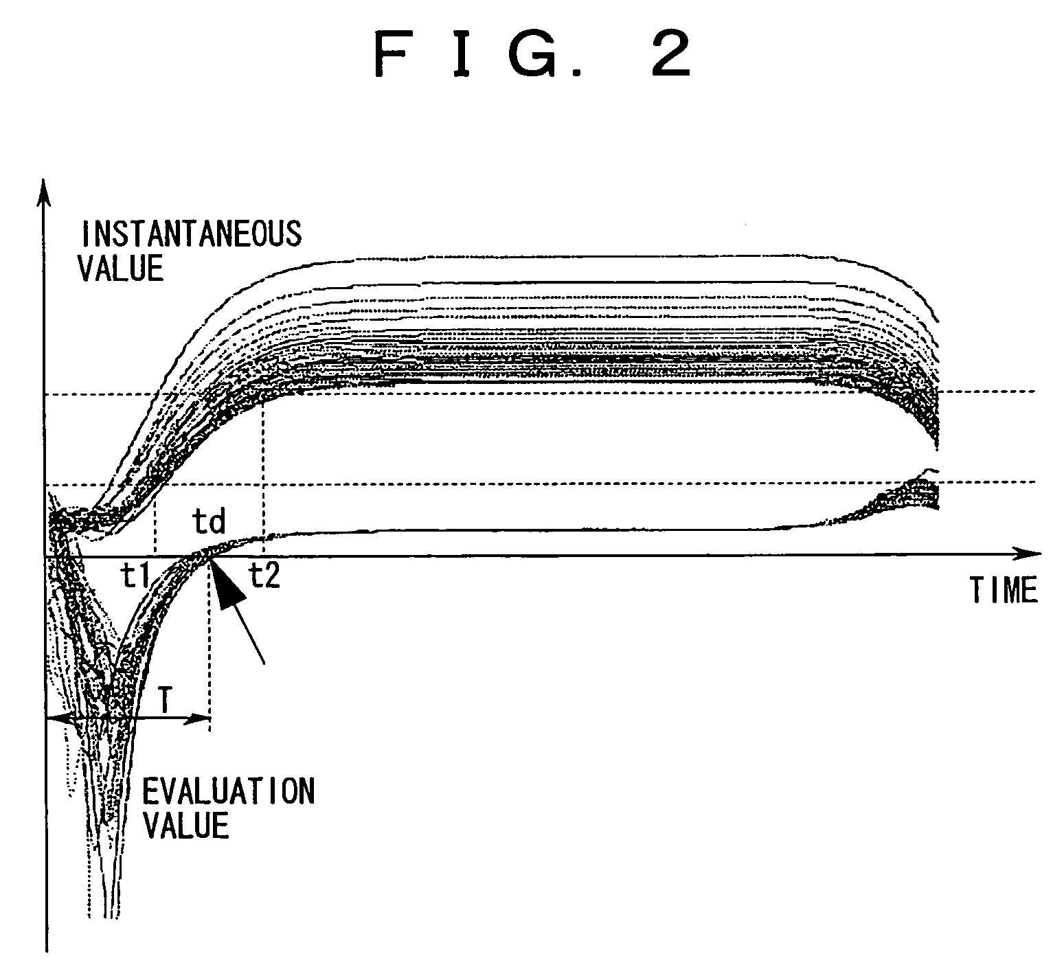
[0151]FIG. 2 is a diagram illustrating an operation of the first embodiment of the present invention.

[0152]Hereinafter, the first embodiment of the present invention will be described with reference to FIGS. 1 and 2.

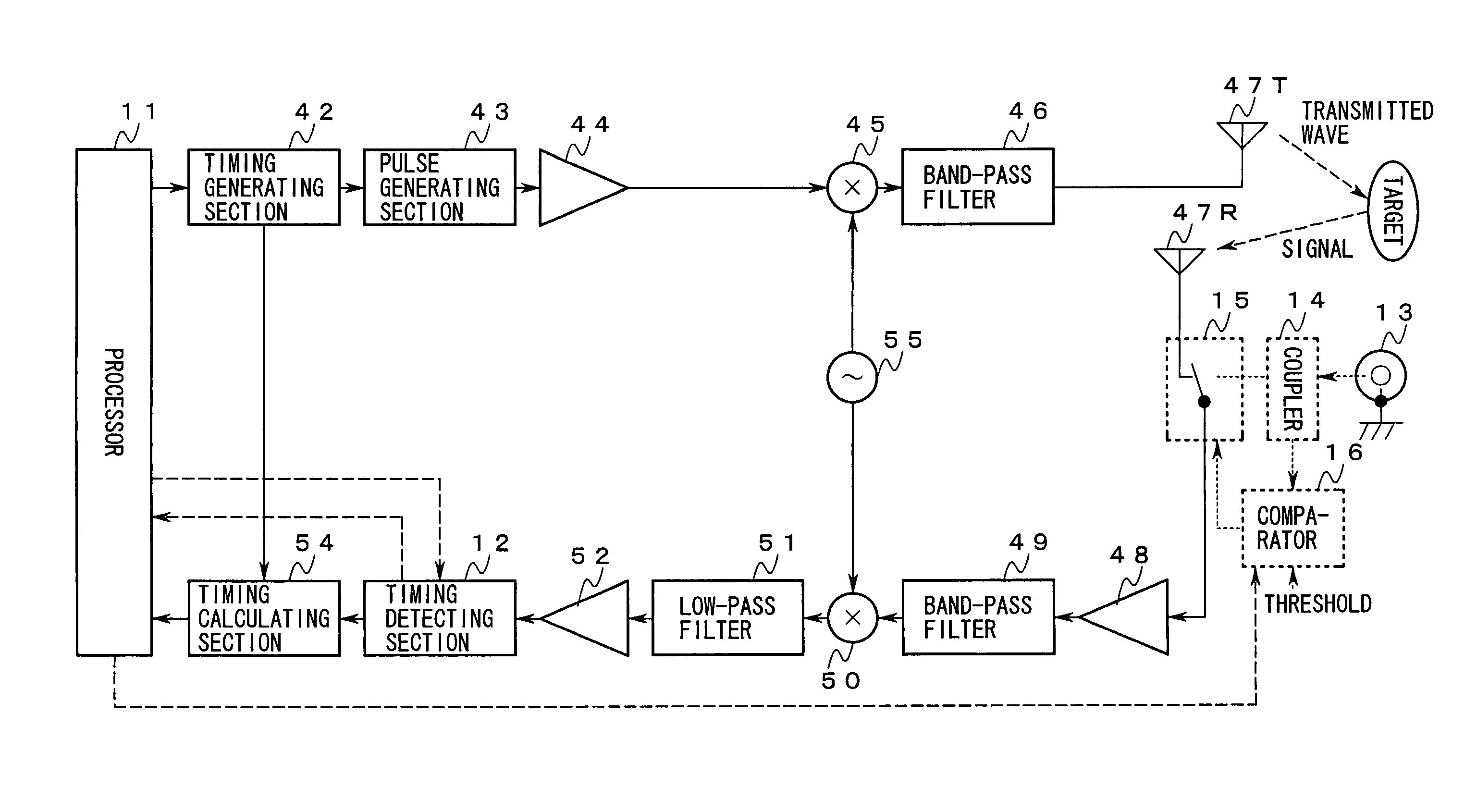
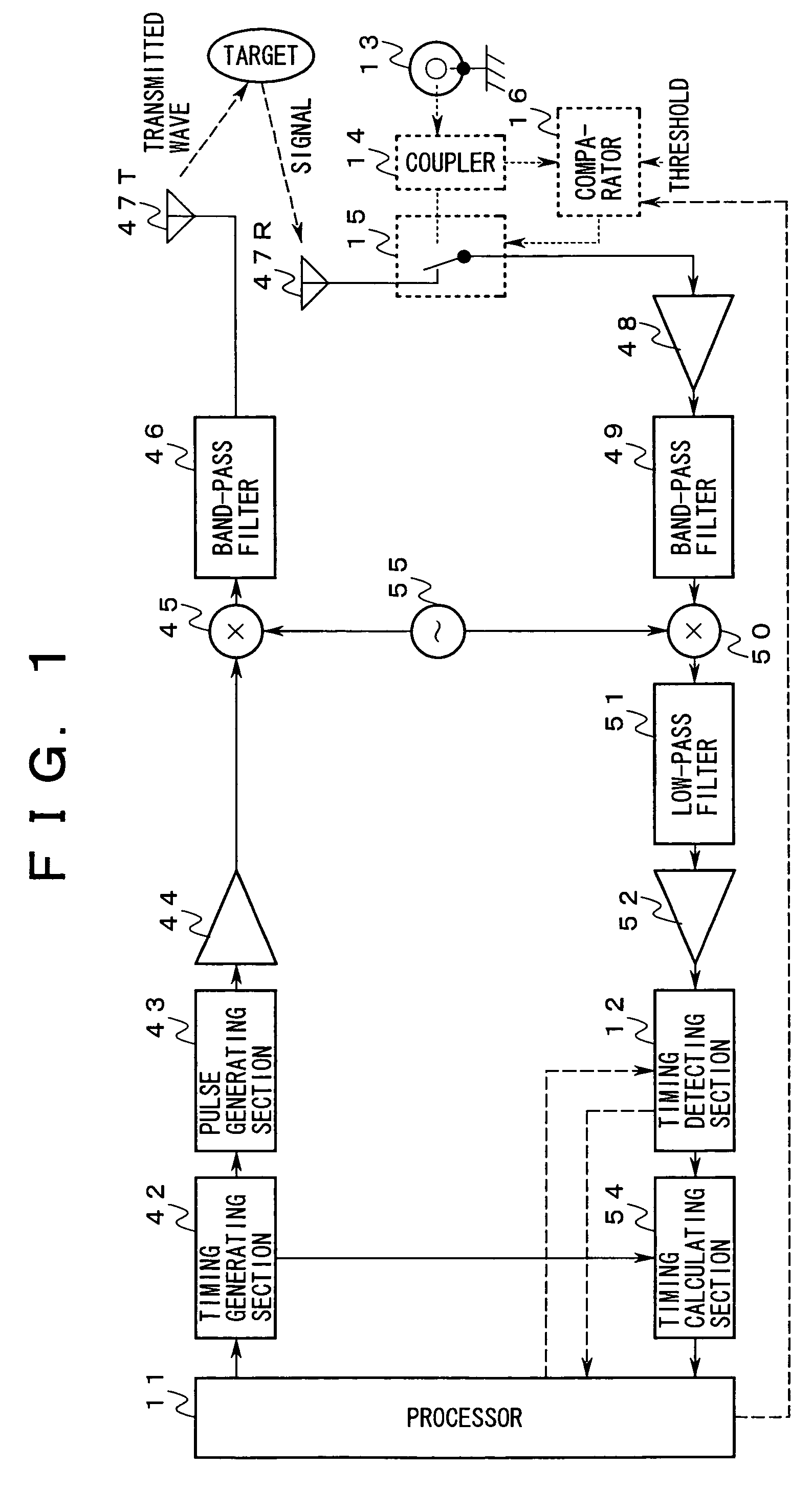
[0153]A timing generating section 42, a pulse generating section 43, an amplifying section 44, a modulating section 45, and a band-pass filter 46 emits a transmitted wave having small initial value and pulse width (duty ratio) to an extent that an amplifying section 48, a band-pass filter 49, a demodulating section 50, a low-pass filter 51, and an amplifying section 52 respond nonlinearly via an antenna 47T in a period (hereinafter, referred to as linear response period) that the above-described base band signal rises.

[0154]Further, an instance τ0 at which a pulse signal corresponding to the above-described pulse signal is to be detected from the base band signal generated under a homodyne detection of a signal arriving from a target according to such a...

second embodiment

[Second Embodiment]

[0170]Hereinafter, the second embodiment will be described.

[0171]In the present embodiment, as shown in a dotted line of FIG. 1, specified output and input of a timing detecting section 12 are connected to corresponding ports of the processor 11 respectively. Further the following elements are provided:

[0172]A coaxial connector 13;

[0173]A coupler 14 whose input is connected to the coaxial connector 13;

[0174]A switch 15 having a make contact connected to an output of the coupler 14, a common contact connected to an input of the amplifying section 48, and a break contact connected to a feeding point of the antenna 47R; and

[0175]A comparator 16 which is connected to the other output of the coupler 14 and a control input of the switch 15 and to which a threshold described later is given in advance.

[0176]Hereinafter, the operation of the second embodiment will be described with reference to FIG. 1.

[0177]The comparator 15 maintains the connection of the common contact a...

third embodiment

[Third Embodiment]

[0187]FIG. 3 is a diagram showing a third embodiment of the present invention.

[0188]In the present embodiment, as shown in FIG. 3, the following elements are provided:

[0189]A directional coupler 21 appended to a feeding line of the antenna 47T; and

[0190]A reference value generating section 22 which is connected in series to one terminal connected to an auxiliary line provided in the directional coupler 21 and whose output is connected to a corresponding input of the timing detecting section 12.

[0191]Hereinafter, the operation of the third embodiment will be described with reference to FIG. 3.

[0192]The directional coupler 21 extracts components of the transmitted wave which is fed to the antenna 47T.

[0193]The reference value generating section 22 demodulates the components, on behalf of the demodulating section 50, to generate the base band signal and samples the instantaneous values of the base band signal in the period Δ to calculate the ratio B′(t) (=y′(t) / y′(t+Δ...


PUM


Abstract

The invention relates to a radar device for measuring a relative distance to a target. It is an object of the invention to precisely determine the relative distance to the target in a wide range. The radar device according to the invention generates a second pulse by demodulating a signal arriving from a target as a response to a wave signal modulated with a first pulse. The radar device evaluates, as the relative distance to the target, such two different instances that an absolute value of a deviation of a ratio of two instantaneous values of the second pulse from a reference value as a ratio of two instantaneous values of the first pulse is to be minimum. The respective two instantaneous values are with a predetermined interval therebetween on a time axis.

Description

CROSS-REFERENCE TO RELATED APPLICATION[0001]This application is a continuation application of International Application PCT / JP03 / 05279 filed Apr. 24, 2003, and designating the U.S. the contents of which are herein wholly incorporated by reference.BACKGROUND OF THE INVENTION[0002]1. Field of the Invention[0003]The present invention relates to a radar device for measuring the relative distance to a target by processing a signal arriving from the target as a response to an irradiated wave signal.[0004]2. Description of the Related Art[0005]In recent years, with the application of highly advanced information processing technologies, image processing technologies, and signal processing technologies, enhancements in performance and value added of a radar device are achieved, and thus the radar device is applied to various fields.[0006]Among these fields, for example, in a vehicle such as an automobile or the like, for the purpose of ensuring safety when traveling or driving, the radar dev...

Claims


Application Information

Patent Timeline
IPC IPC(8): G01S13/10G01S13/93
CPCG01S13/103
Inventor YOKOO, KAORUOISHI, YASUYUKI
Owner FUJITSU LTD
Why Eureka
Try Eureka