Method of inspecting impacts observed in fan casings

a technology of impact inspection and fan casing, which is applied in the direction of efficient propulsion technologies, machines/engines, instruments, etc., can solve the problems of increasing the number of technical validation requests, affecting the quality of parts, and the inability to meet the requirements of inspection,

Active Publication Date: 2016-11-15
SN DETUDE & DE CONSTR DE MOTEURS DAVIATION S N E C M A
View PDF7 Cites 0 Cited by
  • Summary
  • Abstract
  • Description
  • Claims
  • Application Information

AI Technical Summary

Benefits of technology

[0011]The object of the invention offers a solution to the problems just set out by providing a simplified inspection method, making the task easier for controllers; the invention aims at simply evaluating the harmfulness of observed impacts in order to accelerate the processing of these defects. To do this, the present invention provides use of simple inspection tools, which require no particular training for use thereof, which substantially enable determining distances between different impacts to be avoided while allowing to quickly rule on whether these defects are accepted as to the specific retention of the fan casing.

Problems solved by technology

Repairing defects created by the abovementioned impacts has been contemplated by welding methods; but conventional welding processes, known as TIG, have been contemplated to refill these impacts but the conventional processes (TIG) do not yield satisfactory results, in particular on aluminium casings.
Since such repairing is not applicable, this led, when impacts had high dimensions, to replace the full casing, or to dismount the engine.
However, with the ageing of the fleet and the increasing number of engines in operation, these recurrent defects led to an increasing number of technical validation requests, and delays caused to restoration of parts subjected to the observed defects.
Unfortunately, these acceptance criteria only enable a restricted number defect to be accepted, because of the requirement to have available comparable reference values, and therefore do not prevent the number of requested validations from being increased; to overcome this problem, new acceptance criteria should constantly be introduced at each new noticed defect, which is not a viable solution in the long term.
Furthermore, in view of the number of trinomials of values yet available, this inspection method may come out to be heavy and complex for controllers.

Method used


Image

  • Method of inspecting impacts observed in fan casings
  • Method of inspecting impacts observed in fan casings
  • Method of inspecting impacts observed in fan casings

Examples


Embodiment Construction

[0039]Unless otherwise set out, a same element appearing in different figures has a single reference.

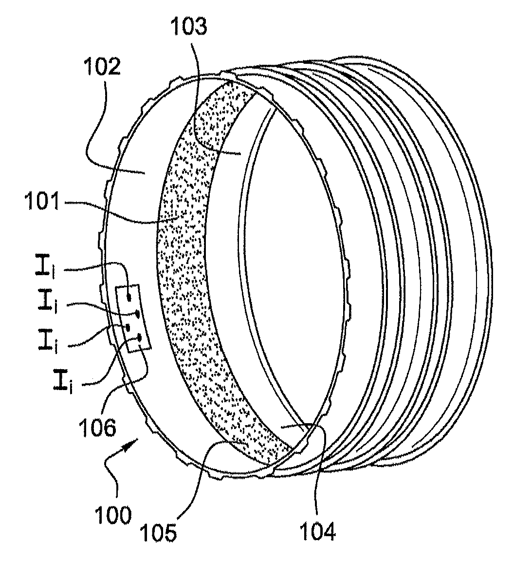
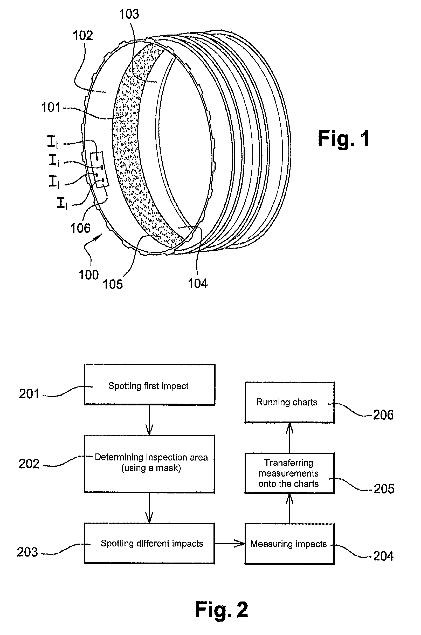
[0040]In FIG. 1, the fan casing 100 has been represented, which is typically of aluminium. A plurality of vanes, not shown, are usually provided by forming a disk inside the casing 100.

[0041]The casing 100 has an internal face 104, a central part 101 of which has an abradable zone 105. In practice, the abradable zone 105 is provided facing the vanes; its function is to restrict the deterioration in the casing when the vanes slightly rub on the internal face 104.

[0042]On either side of the abradable zone, there are respectively an upstream zone 101, which is the first zone met by air entering the casing 100, and a downstream zone 103, which is the zone through which air passes once the same has been accelerated by the moving vanes.

[0043]FIG. 2 is a diagram illustrating an exemplary implementation of the method according to the invention.

[0044]In this figure, the successive steps to be...


PUM

PropertyMeasurementUnit
widthaaaaaaaaaa
widthaaaaaaaaaa
lengthaaaaaaaaaa

Abstract

A method for inspecting impacts present on an internal face of a fan casing, the method including: spotting a first impact present on the internal face of the fan casing; delimiting an inspection area containing the first impact; spotting the various impacts present in the delimited inspection area, the various spotted impacts forming a set of impacts to be considered; measuring, for each impact that is to be considered, the depth of length of the impact; for each impact to be considered, determining a harmfulness value, using at least one chart relating the depth and length of each impact to be considered to a level of harmfulness; determining, for the inspection area containing the first impact, a total harmfulness value by adding together the harmfulness level determined for each impact to be considered.

Description

CROSS-REFERENCE TO RELATED APPLICATIONS[0001]This is the U.S. National Stage of PCT / FR2012 / 050542, filed Mar. 15, 2012, which in turn claims priority to French Patent Application No. 1152492, filed Mar. 25, 2011, the entire contents of all applications are incorporated herein by reference in their entireties.TECHNICAL FIELD OF THE INVENTION[0002]The present invention relates to a method for inspecting impacts observed in fan casings of aircraft engines.[0003]The field of the invention is generally that of aircraft engines, and more particularly that of monitoring the condition of these engines over the course of time. The present invention more precisely relates to fan casings; it is reminded that in such a context, a fan is generally a multiple shrouded propeller, which can be mounted in the front or even in the rear of jet engines, and the function of which is to promote an increase in the thrust generated by the jet engine, by accelerating the huge air mass passing therethrough b...

Claims


Application Information

Patent Timeline
Patent Type & Authority Patents(United States)
IPC IPC(8): G01M13/00B64C5/06F01D21/00F01D21/04G01N21/954G01N21/88G01B3/00G01N17/00B64D45/00B64C3/14
CPCG01M13/00B64C5/06F01D21/003F01D21/045G01N21/8803G01N21/954B64C2003/146B64D2045/0095F05B2280/6003F05D2260/80G01B3/00G01N17/00Y02T50/672Y02T50/60B23P6/00B64D33/02G01N21/88
Inventor TRAN, JULIENLAVIGNOTTE, RICHARD
Owner SN DETUDE & DE CONSTR DE MOTEURS DAVIATION S N E C M A
Why Eureka
Try Eureka