
Wall and construction method for same

a construction method and wall technology, applied in the direction of walls, constructions, building components, etc., can solve the problems of not only ensuring the strength and achieve the effect of easy wall formation and better protection of the keel fram

Active Publication Date: 2019-05-28
DONGGUAN SHIXI INTELLIGENT MACHINE MFG
View PDF22 Cites 0 Cited by
  • Summary
  • Abstract
  • Description
  • Claims
  • Application Information

AI Technical Summary

Benefits of technology

The patent text describes a wall structure that uses various mounting and trimming techniques to provide durability and protect against damage and corrosion. The wall is made from lightweight materials, such as ferrous materials, which are easy to install. The wall also includes a spacing strip to accurately determine the distance between panels and prevent theft. Additionally, there are corrugated panels to absorb shock and protect against heat, fire, and sound. Overall, the wall structure is efficient to install and provides excellent protection against damage and corrosion.

Problems solved by technology

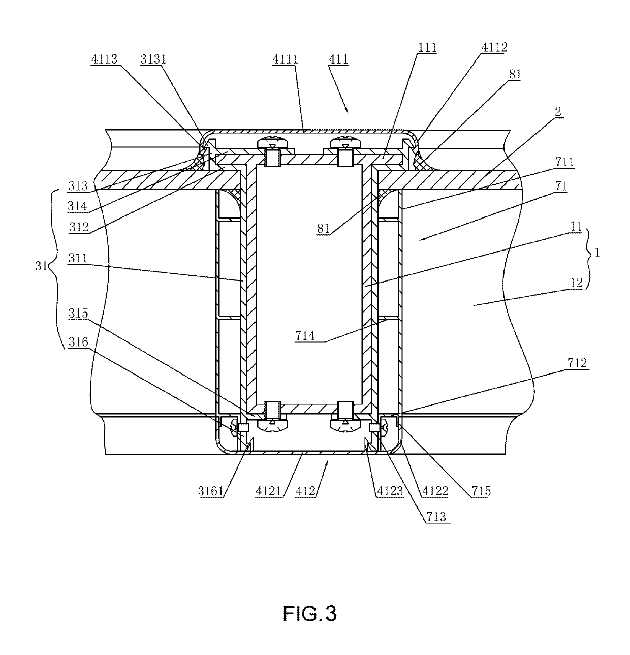
Therefore, it can not only ensure the strength of the keel frame but also protect the keel frame through the transverse mounting strips, the longitudinal mounting strips, the transverse outer trim strips, the longitudinal outer trim strips, the transverse inner trim strips, the longitudinal inner trim strips cladding the keel frame to protect the keel frame against corrosion.

Method used


Image

  • Wall and construction method for same
  • Wall and construction method for same
  • Wall and construction method for same

Examples


embodiment 1

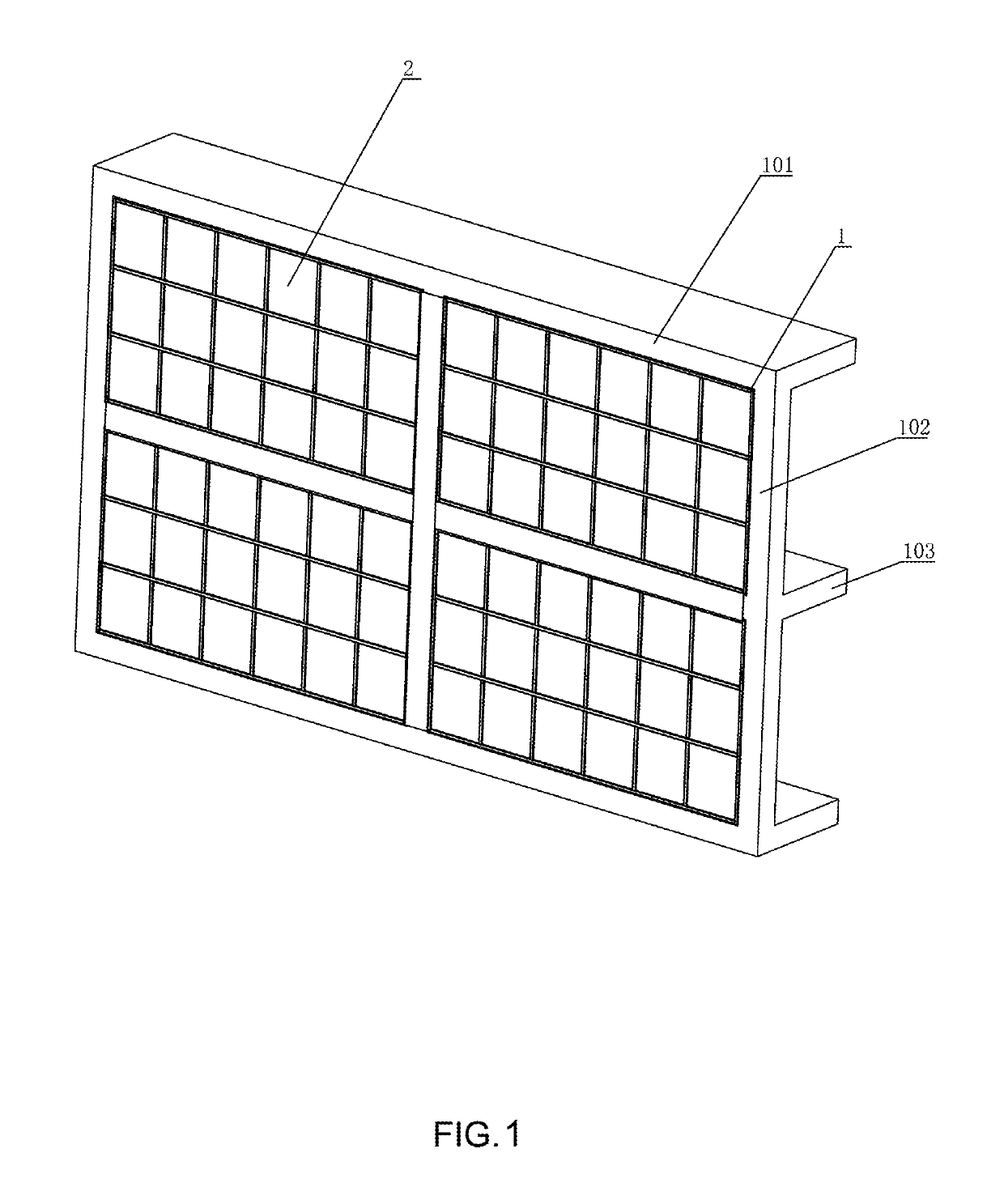
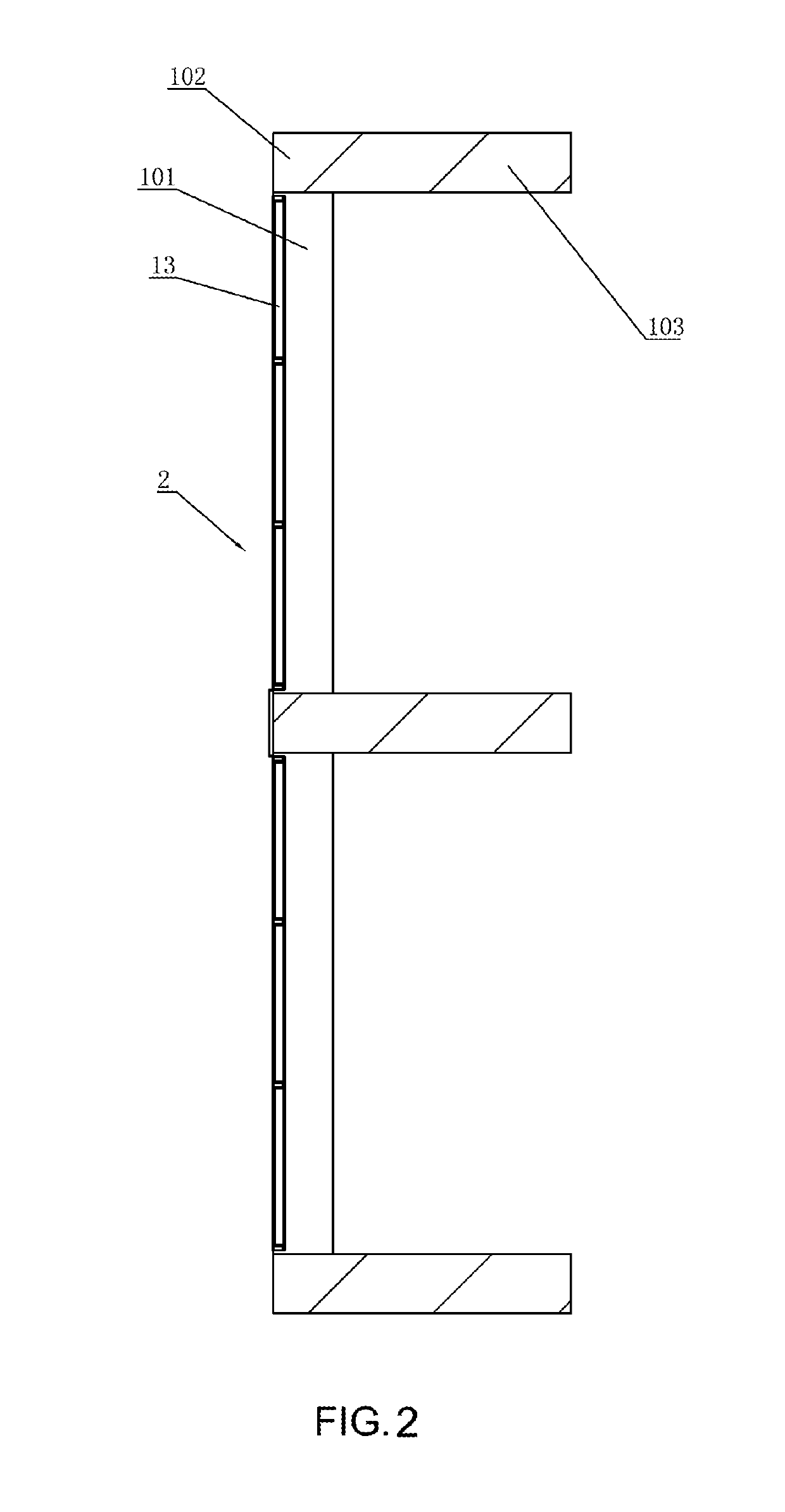
[0050]As shown in FIG. 1 and FIG. 2, the wall comprises a main body comprising beams 101, uprights 102 and floor slabs 103, wherein the uprights 102 are formed between beams 101, and the floor slabs 103 and the beams 101 are mutually connected. As shown in FIG. 3 and FIG. 4, the wall also comprises a keel frame 1 comprising more than two longitudinal keels 11 and more than two transverse keels 12, the keel frame 1 is installed in a space formed by the uprights 102 and the floor slabs 103, the longitudinal keels 11 on the left and right sides of the keel frame 1 located within the space are fixed to the inner side faces of the uprights 102, the uppermost and undermost transverse keels 12 are fixed to the inner side faces of the beams 101, and the said keel frame 1 can be either flush with or protrude from the outer surface of the beams 101. Cells 13 are formed between adjacent transverse keels 12 and adjacent longitudinal keels 11; the panel units 2 are installed in the Cell 13; a lo...

embodiment 2

[0086]Relative to the embodiment 1, the material selection of the longitudinal and transverse mounting strips herein is not typical at all. In this embodiment 1, the aluminum alloy material is selected for the longitudinal and transverse mounting strips, which results in lower heat insulation performance Relative to the embodiment 1. Others are the same as those of the embodiment 1.

embodiment 3

[0087]Relative to the embodiment 2, in order to select the aluminum profile for the longitudinal and transverse mounting strips and improve the heat insulation performance, the outer heat resisting sheet may be arranged between the transverse mounting strip and transverse outer trim strip, a transverse inner heat resisting sheet is arranged between the transverse mounting strip and the transverse inner trim strip; a longitudinal outer heat resisting sheet is arranged between the longitudinal mounting strip and the longitudinal outer trim strip, a longitudinal inner heat resisting sheet is arranged between the longitudinal mounting strip and the longitudinal inner trim strip. Of course, the longitudinal mounting strip and the transverse mounting strip can also be wrapped with a plastic sheet respectively. Others are the same as those of the embodiment 2.


PUM


Abstract

The present invention discloses a wall and a construction method. The wall comprises keel frames comprising transverse keels and longitudinal keels, cells are formed between adjacent transverse keels and adjacent longitudinal keels; each panel unit is installed in each cell; each panel unit is installed in each cell; transverse mounting strips are arranged between the transverse keels and the panel units, and longitudinal mounting strips are arranged between the longitudinal keels and the panel units; the transverse mounting strip stretches across the transverse keel, the longitudinal mounting strip stretches across the longitudinal keel; outdoor and indoor position corresponding to the transverse keel is provided with a transverse outer trim strip and a transverse inner trim strip; outdoor and indoor position corresponding to the longitudinal keel is provided with a longitudinal outer trim strip and a longitudinal inner trim strip. The present invention can better protect the keel frames, and easy to form a wall.

Description

CROSS REFERENCE TO RELATED APPLICATIONS[0001]This application is a national stage filing under section 371 of International Application No. PCT / CN2014 / 072921 filed on Mar. 5, 2014, and published in Chinese on Sep. 11, 2015 as WO 2015 / 131354.TECHNICAL FIELD[0002]The invention relates to a wall and a wall construction method.BACKGROUND OF THE INVENTION[0003]A wall is an important part of a building. It has the function of bearing, enveloping or separating space. A wall is divided by wall stress and material into bearing wall and non-bearing wall, and by wall construction mode into solid wall, sintered hollow brick wall, rowlock wall and composite wall. A curtain wall is an exterior wall envelope for buildings, which is not for load-bearing and hang up like a curtain, so it is also known as the suspended wall. The curtain wall is a common light weight wall with a decorative effect for large high-rise modern buildings. The existing curtain wall consists of a structural frame and inlaid ...

Claims


Application Information

Patent Timeline
Patent Type & Authority Patents(United States)
IPC IPC(8): E04B2/90
CPCE04B2/90
Inventor YANG, DONGZUO
Owner DONGGUAN SHIXI INTELLIGENT MACHINE MFG
Learn More