Oil return mechanism

a technology of oil return mechanism and oil, which is applied in the direction of liquid fuel engine, process and machine control, instruments, etc., can solve the problems of adding significant cost to the oil return mechanism and the failure of the oil return mechanism to meet industrial requirements, etc., and achieves simple structure, convenient manufacture, and reduced flow of liquid

Active Publication Date: 2017-11-07
CHANGSHU TONGRUN AUTO ACCESSORY
View PDF7 Cites 1 Cited by
  • Summary
  • Abstract
  • Description
  • Claims
  • Application Information

AI Technical Summary

Benefits of technology

[0002]To overcome the defects described above, the present invention provides an oil return mechanism which can regulate a speed of a fluid flowing from a liquid returning cavity to the communicating cavity, and reduce costs efficiently.
[0014]In use, when the first blocking ball moves to the open position of the blocking position, the fluid can flow to the communicating cavity through the second communicating cavity or the liquid guiding gap, to reduce the amount of the flowing liquid, and thus regulate the speed of the fluid flowing from the liquid returning cavity to the communicating cavity. Moreover, the present invention has the advantages of simple structure, convenient manufacture and great reduction of cost. The liquid guiding gap formed between the first blocking ball and an inner wall of the communicating portion has an advantage of avoiding clogging.

Problems solved by technology

However, when the control switch is on, the speed of the fluid flowing from the liquid returning cavity to the communicating cavity remains stable, and thus the jack descends rapidly either in a no load condition or in a load condition, which may result in accidents, for instance, a lifting load rapidly falling down from the operating jack to hurt an operator.
However, the expensive speed regulating device adds significant cost to the oil return mechanism, and thus the oil return mechanism fails to satisfy industrial require's.

Method used


Image

  • Oil return mechanism
  • Oil return mechanism
  • Oil return mechanism

Examples


Embodiment Construction

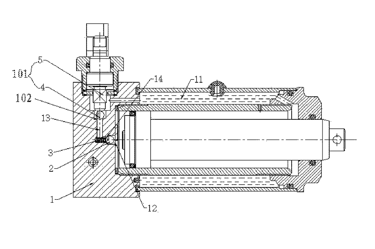
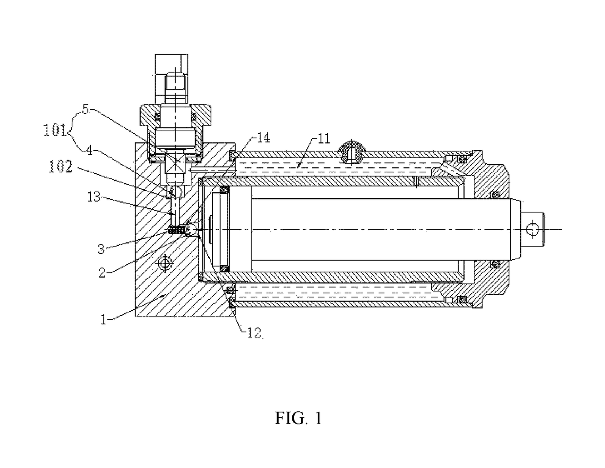
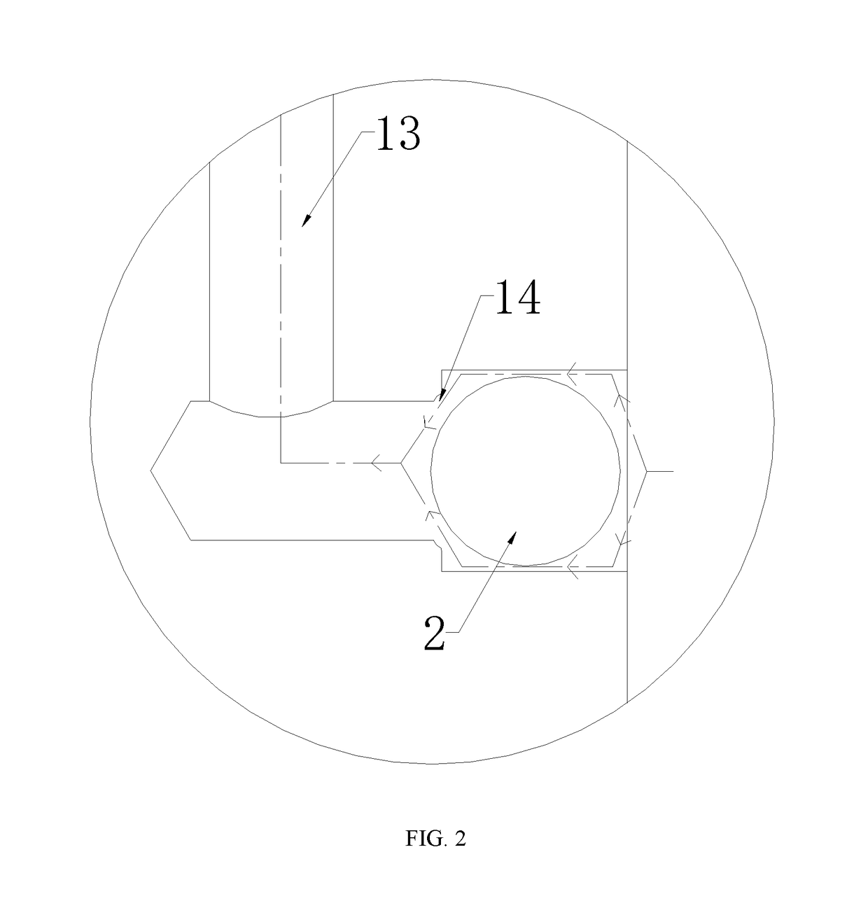
[0021]Referring to the FIG. 1 to FIG. 3, an oil return mechanism includes a base 1, a control switch 101; a first blocking ball 2 mounted in the base 1, an elastic member 3 mounted between the first blocking ball 2 and the base 1. The base 1 has a liquid storing cavity 11, a liquid returning cavity 12, a communicating cavity 13, a first communicating opening 14 communicating between the liquid returning cavity 12 and the communicating cavity 13, and a second communicating opening 102 communicating between the communicating cavity 13 and the liquid storing cavity 11. The control switch 101 is adapted for controlling the second communicating opening 102 open or closed so that the communicating cavity 13 and the liquid storing cavity 11 are connected or separated. The first blocking ball 2 moves between a blocking position and an open position with an external force. When the first blocking ball 2 is in the open position, the whole first communicating opening 14 is open, and thus a flu...


PUM


Abstract

An oil return mechanism includes a base, a control switch, a first blocking ball mounted in the base, an elastic member mounted between the first blocking ball and the base. The base has a liquid storing cavity, a liquid returning cavity, a communicating cavity, a first communicating opening communicating between the liquid returning cavity and the communicating cavity, and a second communicating opening communicating between the communicating cavity and the liquid storing cavity. The present invention can regulate a speed of a fluid flowing from the liquid returning cavity to the communicating cavity, and has the advantages of simple structure and great reduction of cost.

Description

BACKGROUND[0001]A jack is generally configured with an oil return mechanism. A conventional oil return mechanism includes a liquid storing cavity, a liquid returning cavity, and a communicating cavity communicating between the liquid storing cavity and the liquid returning cavity. The communicating cavity is configured with a control switch for selectively conducting the on-off control of the communicating cavity. A speed of a fluid flowing from the liquid returning cavity to the communicating cavity has a direct impact on a descending speed of the jack in operation. However, when the control switch is on, the speed of the fluid flowing from the liquid returning cavity to the communicating cavity remains stable, and thus the jack descends rapidly either in a no load condition or in a load condition, which may result in accidents, for instance, a lifting load rapidly falling down from the operating jack to hurt an operator. Therefore, the conventional oil return mechanism is configur...

Claims


Application Information

Patent Timeline
Patent Type & Authority Patents(United States)
IPC IPC(8): B66F3/25F15B1/26G05D7/01F16K17/20F15B15/20F04B53/16F15B15/14
CPCB66F3/25F04B53/16F15B1/26F15B15/20F15B15/202F16K17/20G05D7/0133G05D7/0186F15B15/204Y10T137/7847F15B15/1428F15B15/1433F15B13/021F16K1/14F16K15/044
Inventor CHEN, JIANGYE, JUNXUEWANG, JINGFANG
Owner CHANGSHU TONGRUN AUTO ACCESSORY
Why Eureka
Try Eureka