Motor vehicle door lock

a technology for motor vehicles and door locks, applied in carpet fasteners, dwelling equipment, applications, etc., can solve the problems of relatively complicated design of motor vehicle door locks, and achieve the effect of reducing the complexity of the construction as a whole and achieving synergy effects

Active Publication Date: 2017-11-07
KIEKERT AG
View PDF45 Cites 14 Cited by
  • Summary
  • Abstract
  • Description
  • Claims
  • Application Information

AI Technical Summary

Benefits of technology

[0009]The invention is based on the technical problem of further developing such a motor vehicle door lock is such a way that the complexity of the construction as a whole is reduced and synergy effects can be used.
[0013]In this way, the overall complexity is reduced and synergy effects between the drives can be used, in this case for the emergency interruption of the closing function. This reduces manufacturing costs and increases functional reliability.
[0015]In this way not only a comfortable closing operation is provided but overall reliability is also increased, as the invention ensures that a motor vehicle door interacting with the motor vehicle door lock is transferred in any case into its main locking position and that thus, in case of an accident, all safety devices inside the motor vehicle door can become effective as planned.
[0019]As a result, the closing pawl is also pivoted and ensures, in turn, that the rotary latch is closed, as described. The closing drive can act upon the closing transfer lever mechanically and / or electrically thus ensuring the described pivoting. The closing transfer lever can be mounted on the same axis as the rotary latch, resulting in an overall compact arrangement.
[0029]As a result, the rotary latch can, during the interruption of the closing function, be freely pivoted from its initial closed position into its open position by means of a spring and the previously engaged motor vehicle door is released.

Problems solved by technology

Such motor vehicle door locks do, however, have a relatively complicated design, in particular where they should also provide the option of providing an emergency interruption of the closing operation.

Method used


Image

  • Motor vehicle door lock
  • Motor vehicle door lock
  • Motor vehicle door lock

Examples


Embodiment Construction

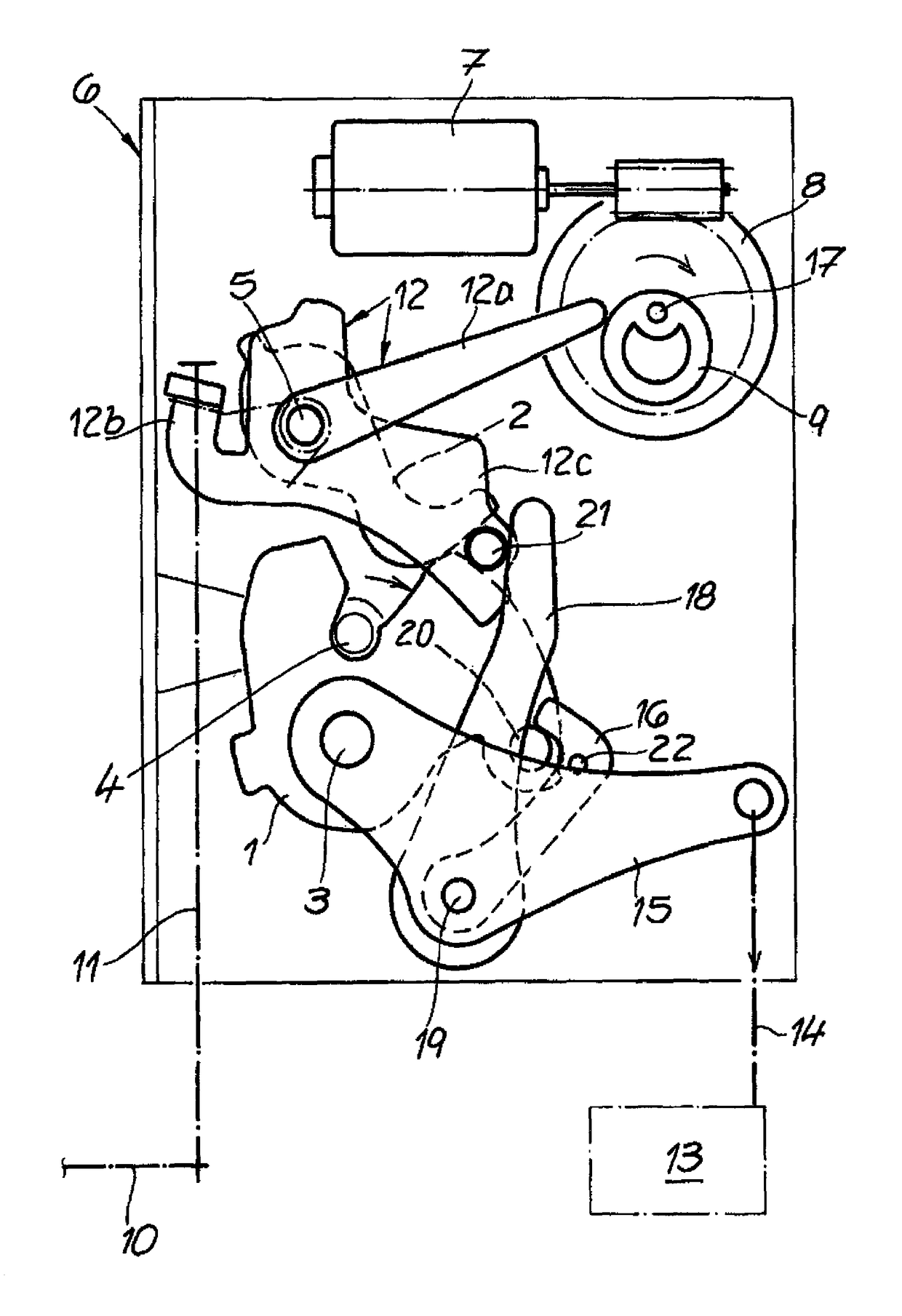
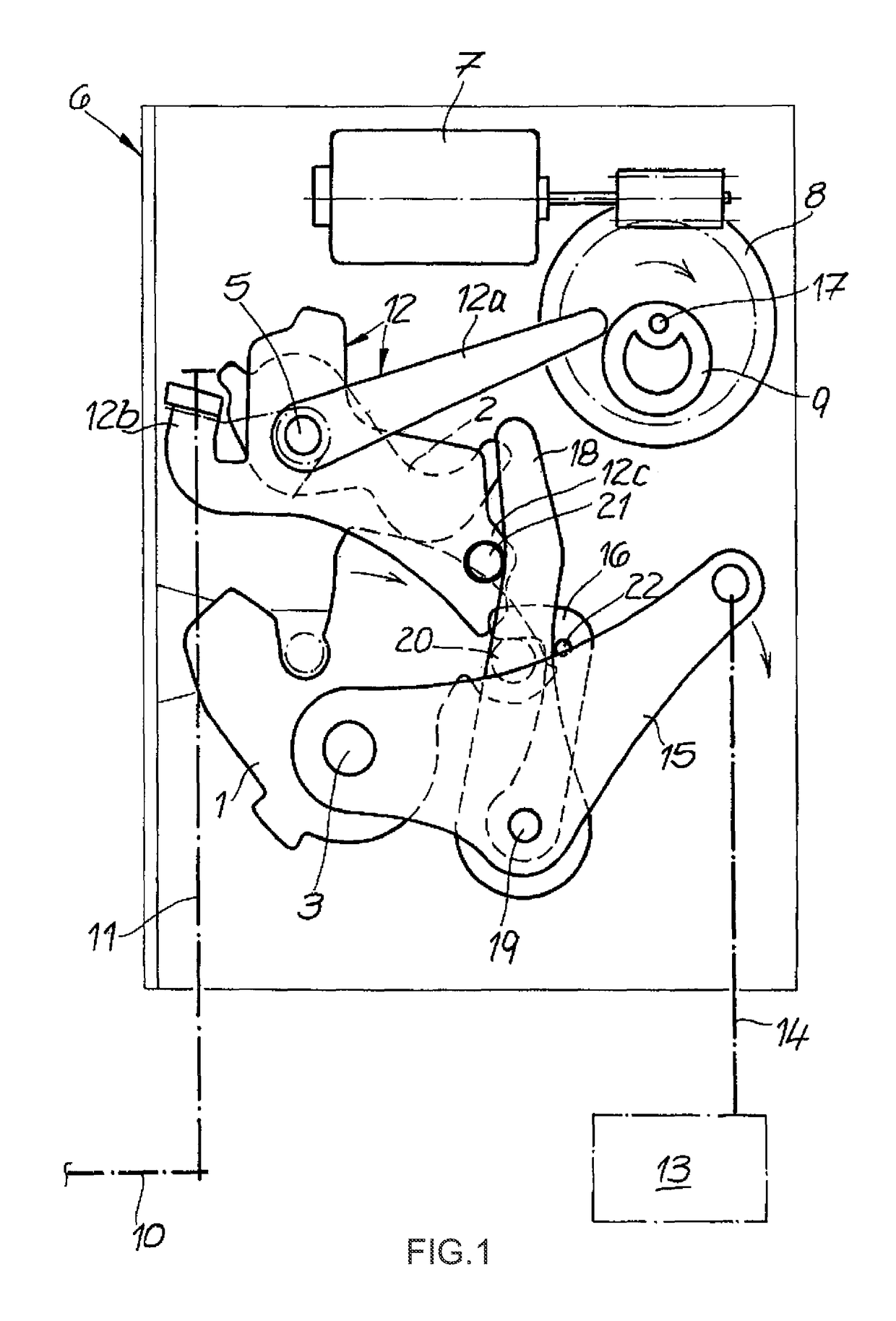
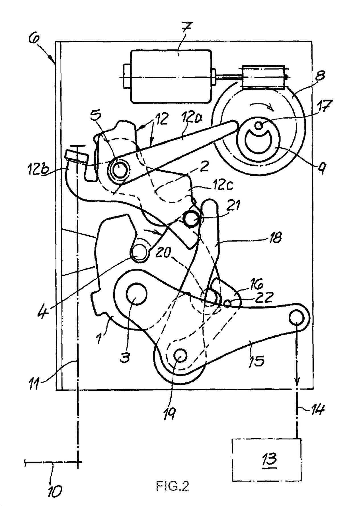
[0039]The exemplary figures show a motor vehicle door lock equipped in the usual manner with a locking mechanism 1, 2 consisting of a rotary latch 1 and a pawl 2. As soon as the rotary latch 1 has assumed its main locking position shown in FIG. 2 or its closed position, the pawl 2 engages and blocks the rotary latch 1. In the shown example no latched connection occurs strictly speaking between the pawl 2 on one hand and the rotary latch 1 on the other hand in the main locking position or a preceding intermediate locking position. These terms should, however, be used for the below explanations. The main locking position is usually identified by a main closing position or closed position, whilst the intermediate locking position is part of an initial closed position.

[0040]Once the rotary latch 1 is no longer blocked by the pawl 2, the rotary latch 1 can mum anticlockwise around its axis 3 due to the force of the spring—not expressly shown—and assumes the open position. During this ope...


PUM


Abstract

A motor vehicle door lock comprising a locking mechanism (1, 2) and a closing / opening device (7 to 16) with at least one drive (7 to 11 and 13, 14), at least one transfer element (12, 15) and a driving pawl (16), in which the drive acts on the driving pawl with the assistance of the transfer element to open and close the locking mechanism, wherein a mechanical and / or electrical opening drive (7 to 11) and a mechanical and / or electrical closing drive (13, 14) each with a respective opening transfer lever (12) and closing transfer lever (15) are provided, in which the opening drive (7 to 11) including the opening transfer lever (12) in addition to the opening function for the locking mechanism (1, 2) is also designed to interrupt a closing function initiated by the closing drive (13, 14) in connection with the closing transfer lever (15).

Description

CROSS REFERENCE TO RELATED APPLICATIONS[0001]This application claims priority under 35 U.S.C. 119 and 35 U.S.C. 365 based upon German Patent Application No. 10 2011 012 656.2, filed on Feb. 28, 2011. The entire disclosure of the aforesaid application is incorporated herein by reference.FIELD OF THE INVENTION[0002]The invention relates to a motor vehicle door lock, which is equipped with a locking mechanism and a closing / opening device with at least one drive and at least one transfer element and a driving pawl, in which the drive with the aid of the respective transfer element acts on the driving pawl to open or close the locking mechanism.BACKGROUND OF THE INVENTION[0003]A motor vehicle door lock of the above-mentioned design is, for instance, disclosed in utility patent DE 20 2008 015 789 U1. Closing devices for motor vehicle doors are usually used for moving, for instance, a motor vehicle door from its intermediate locking position into its main locking position. During this proc...

Claims


Application Information

Patent Timeline
Patent Type & Authority Patents(United States)
IPC IPC(8): E05C3/06E05B81/20E05B81/14E05B85/24E05B81/04
CPCE05B81/04E05B81/14E05B81/20E05B85/243Y10T292/1082Y10S292/23Y10T292/108Y10T292/1047E05B81/21E05B77/00
Inventor SCHOLZ, MICHAELMENKE, JOHANNES-THEODORPOHLE, WERNER
Owner KIEKERT AG
Why Eureka
Try Eureka