Coolant-control valve

a technology of valve body and valve body, which is applied in the direction of valve operating means/release devices, machines/engines, mechanical equipment, etc., can solve the problems of affecting the reduction of size and manufacturing cost of the valve, the failure factor of the coolant-control valve, and the inability to provide the initialization learning stopper in the coolant-control valve, etc., to achieve simple and efficient structure and regulate the operating range of the valve body

Active Publication Date: 2017-11-07
MIKUNI CORP
View PDF8 Cites 2 Cited by
  • Summary
  • Abstract
  • Description
  • Claims
  • Application Information

AI Technical Summary

Benefits of technology

[0018]Furthermore, in Patent Literature 2, the stopper is equipped with a stopper of a moving side that is provided on an output shaft of a reduction gear connected to a valve body to rotate the valve body, and a stopper of a fixed side that is provided in a member fixed to the valve housing, so that further rotation of the valve body is adapted to be restricted when both the stoppers come into contact with each other, but there is a concern that these stoppers hinder reduction of size and manufacturing cost of the valve.
[0033]According to embodiments of the present invention, it is possible to regulate the operating range of the valve body by restricting the operating range of the power transmission element on the reduction gear side of the actuator, and it is possible to allow the initialization learning of the operating range of the valve body of the coolant-control valve, based on the restricted operating range. At this time, when the restricting means is provided, the simple and efficient structure can be provided without requiring reinforcement of the structure and enlargement of the size.

Problems solved by technology

However, an initialization learning stopper has not been provided in the coolant-control valve.
Furthermore, Patent Literature 2 has a structure in which, within a rotating range of the rotor (valve body) that eccentrically rotates, there is a portion in which the eccentric rotor comes into contact with a member of a valve seat side, and when the rotor excessively rotates by malfunction of the drive device, the rotor is pressed against the member of the valve seat side, which becomes a factor of failure of the coolant-control valve.
Furthermore, in Patent Literature 2, the stopper is equipped with a stopper of a moving side that is provided on an output shaft of a reduction gear connected to a valve body to rotate the valve body, and a stopper of a fixed side that is provided in a member fixed to the valve housing, so that further rotation of the valve body is adapted to be restricted when both the stoppers come into contact with each other, but there is a concern that these stoppers hinder reduction of size and manufacturing cost of the valve.
For example, in the configuration in which the stopper is provided on the output shaft, since stress may act on a small-diameter portion such as an output shaft in the device, there is a need for a configuration that increases yield strength of the portion provided with the stopper, and there is a concern that it is necessary to increase the size as a configuration that increases the yield strength.
In the case of providing a stopper on the valve body (rotor) connected to the output shaft, a rigid portion is required for a portion provided with the stopper of the valve body, there is a concern that a large load is applied to the rotation shaft of the valve body, and in some cases, there is a need for high strength of the rotation shaft.
There is a concern that these cause an increase in manufacturing cost.
Furthermore, when the restricting means is provided in the valve body or the output shaft, there is a concern that the rigid portion (high-strength portion) may be provided in the valve body, and the high strength of the output shaft may be required.

Method used


Image

  • Coolant-control valve
  • Coolant-control valve
  • Coolant-control valve

Examples


Embodiment Construction

[0039]Hereinafter, preferred embodiments of the present invention will be described with reference to the drawings.

[0040]For example, a rotary type valve is used to control the coolant of an engine of a vehicle, is used by being attached to an engine block of the engine, and is used to open and close a main flow passage and a sub flow passage, in an engine cooling system that has the main flow passage for circulating the coolant between an engine block and a radiator, the sub flow passage for supplying the coolant to a device requiring temperature adjustment using the coolant (for example, a heater or a throttle), and a bypass flow passage that bypasses the radiator.

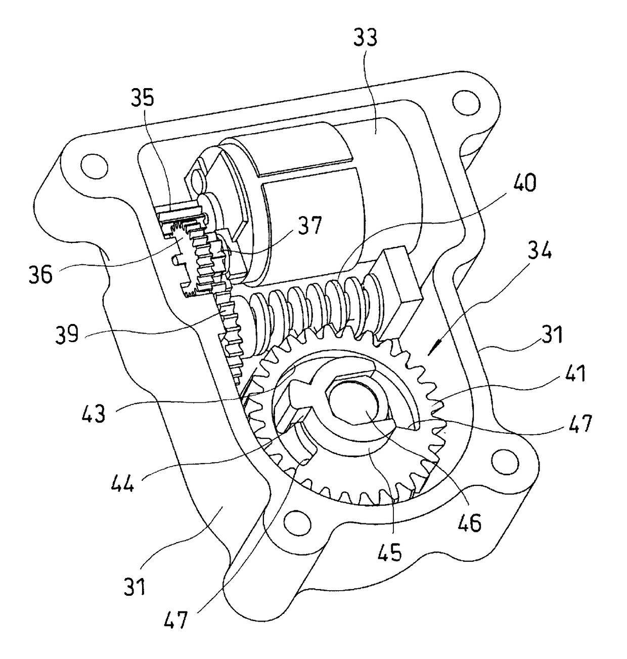
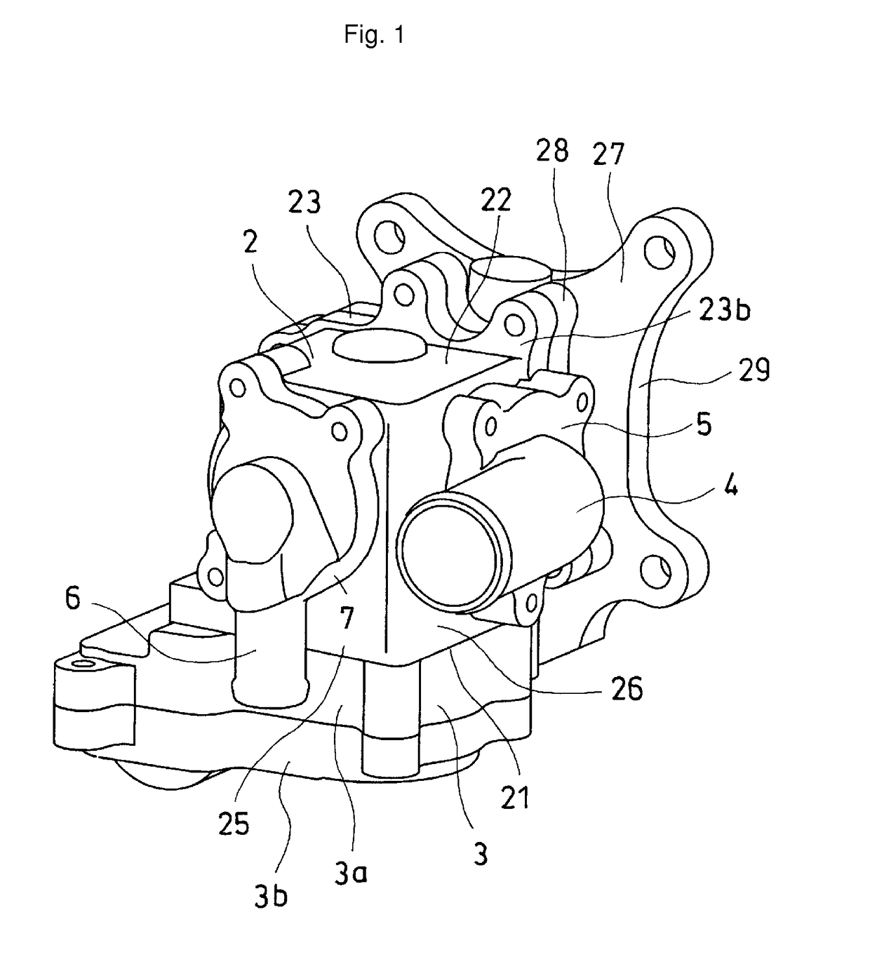
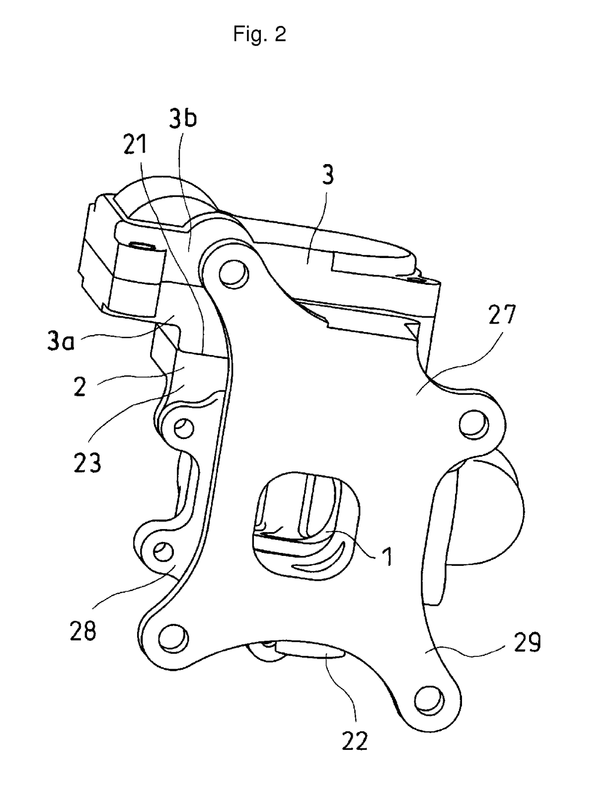
[0041]As illustrated in FIGS. 1 to 3, a rotary type valve has a rotor 1 (illustrated in FIG. 3), a casing 2 that houses the rotor 1 in a freely rotatable manner, a rotary drive device (actuator) 3 that rotationally drives the rotor 1, a main connecting member 5 having a main connecting pipe 4 that is connected to a main ...


PUM


Abstract

A coolant-control valve that performs initialization learning using a stopper and provides an efficient structure by an initialization learning stopper within an actuator which drives a valve body. The coolant-control valve is equipped with a rotor driven to control a flow rate of coolant for cooling an engine, a casing that houses the rotor, and a rotary drive device that drives the rotor. Control means of the rotary drive device have an initialization learning function of an operating range of the rotor. The rotary drive device is equipped with a motor and a reduction gear. The operating range of the rotor is restricted by the operating range of an output gear among power transmission elements in the reduction gear. A groove of the output gear and a fixed-angle stopper inserted into the groove are restricting means for use during initialization learning by the control means.

Description

CROSS-REFERENCE TO RELATED APPLICATION(S)[0001]This application is a continuation application, filed under 35 U.S.C. §111(a), of International Application PCT / JP2013 / 065236, filed on May 31, 2013, which claims the foreign priority benefit of Japanese Patent Application No. 2012-126448, filed Jun. 1, 2012, the disclosures of which are incorporated herein by reference.BACKGROUND[0002]1. Field[0003]Embodiments of the present invention relate to a coolant-control valve that controls the flow of coolant of an engine.[0004]2. Description of Related Art[0005]In an engine (internal combustion engine) of a vehicle such as an automobile, a technique has been studied in which, for the purpose of improvement in warming-up performance of the engine and improvement in fuel efficiency due to operation of the engine at an optimum temperature, apart from a main flow passage that circulates the coolant between the engine and a radiator, a bypass flow passage configured to directly return the coolant ...

Claims


Application Information

Patent Timeline
Patent Type & Authority Patents(United States)
IPC IPC(8): F01P7/14F16K31/04F16K11/085F01P11/14F16K3/24F01P7/16F01P3/20
CPCF01P7/14F01P11/14F16K3/24F16K11/0853F16K31/043F16K31/041F01P2007/146F01P3/20F01P7/16F01P7/167
Inventor TSUCHIYA, TORUOIKAWA, TAKUMIKANESAKA, YOSHIYUKIANDO, SATOSHI
Owner MIKUNI CORP
Why Eureka
Try Eureka