Method for displaying by determined color result image of area extraction result

a color result and image technology, applied in image analysis, texturing/coloring, image enhancement, etc., can solve the problems of unable to determine whether an area is sufficiently extracted, and unclear contour line and mask image range, etc., to achieve the effect of not imposing an extra operation load on the user

Active Publication Date: 2017-11-07
ORMON CORP
View PDF11 Cites 1 Cited by
  • Summary
  • Abstract
  • Description
  • Claims
  • Application Information

AI Technical Summary

Benefits of technology

[0010]One or more embodiments of the present invention provides a technique of allowing a result of area extraction processing on any target image to be displayed with a highly visible color, without imposing an extra operation load on the user.
[0013]By thus determining the displaying color of the extraction result image, when the extraction result image is combined with the target image, the color of the target image is clearly distinguished from the color of the extraction result image, at least in the boundary peripheral area. Thus, the outer edge of the extraction result image, that is, the boundary between the estimated foreground area and the estimated background area, can be visually recognized clearly. Thus, whether the extracted area matches the area intended by the user can be easily determined. With the method, the optimum displaying color of the extraction result image is automatically selected, and thus no extra operation load is imposed on the user.
[0017]According to one or more embodiments of the present invention, in the composite image, the color or the transmittance of the filled area in the extraction result image differs between portions respectively close to or far from the contour of the filled area, or changes towards the portion far from the contour from the portion close to the contour. Thus, the portion close to the contour relatively stands out, whereby a visual effect that the outer edge of the extraction result image becomes clearer can be obtained.
[0018]The following display mode, other than the overlay display, can be employed. For example, according to one or more embodiments of the present invention, the extraction result image is an image in which the boundary line between the estimated foreground area and the estimated background area be drawn with the color determined in the color determination step. Whether the extracted area matches the area intended by the user can also be checked by thus displaying only the boundary line. In this case also, by determining a thickness of the boundary line in accordance with a display resolution of the display device, excellent visibility can be secured for the display device with any level of display resolution. A thickness of the boundary line may also be determined in accordance with an image size of the target image.
[0024]One or more embodiments of the present invention is a result of area extraction processing on any target image can be displayed with a highly visible color, without imposing an extra operation load on a user.

Problems solved by technology

However, there is no guarantee that only a portion, intended by a user, is extracted without fail by performing the processing only once.
However, when the foreground or the background of the original image includes a color similar to the color with which the contour line or the mask image is drawn, the range of the contour line and the mask image becomes unclear.
Thus, whether an area is sufficiently extracted is difficult to be determined, if not impossible.
However, such conventional methods impose an extra operation load on the user.
Furthermore, when the original image includes various hues, an appropriate drawing color might be difficult to determine.

Method used


Image

  • Method for displaying by determined color result image of area extraction result
  • Method for displaying by determined color result image of area extraction result
  • Method for displaying by determined color result image of area extraction result

Examples


first embodiment

[0038](Apparatus Configuration)

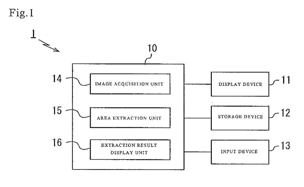
[0039]FIG. 1 schematically shows the configuration of an image processing apparatus having an area extraction function.

[0040]An image processing apparatus 1 includes hardware such as an apparatus main body 10, a display device 11, a storage device 12, and an input device 13. The display device 11 is a device for displaying an image as a target of the area extraction processing, the result of extraction processing, a GUI screen related to the area extraction processing, and the like. For example, a liquid crystal display and the like can be used as the display device 11. The storage device 12 is a device for storing image data, processing result, and the like. For example, an HDD, an SSD, a flash memory, and a network storage may be used as the storage device 12. The input device 13 is a device operated by a user to input an instruction to the apparatus main body 10. For example, a mouse, a keyboard, a touch panel, a dedicated console, and the like can ...

second embodiment

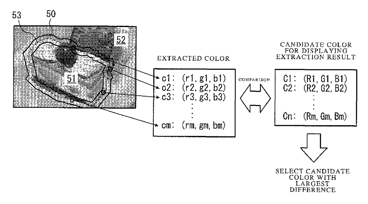
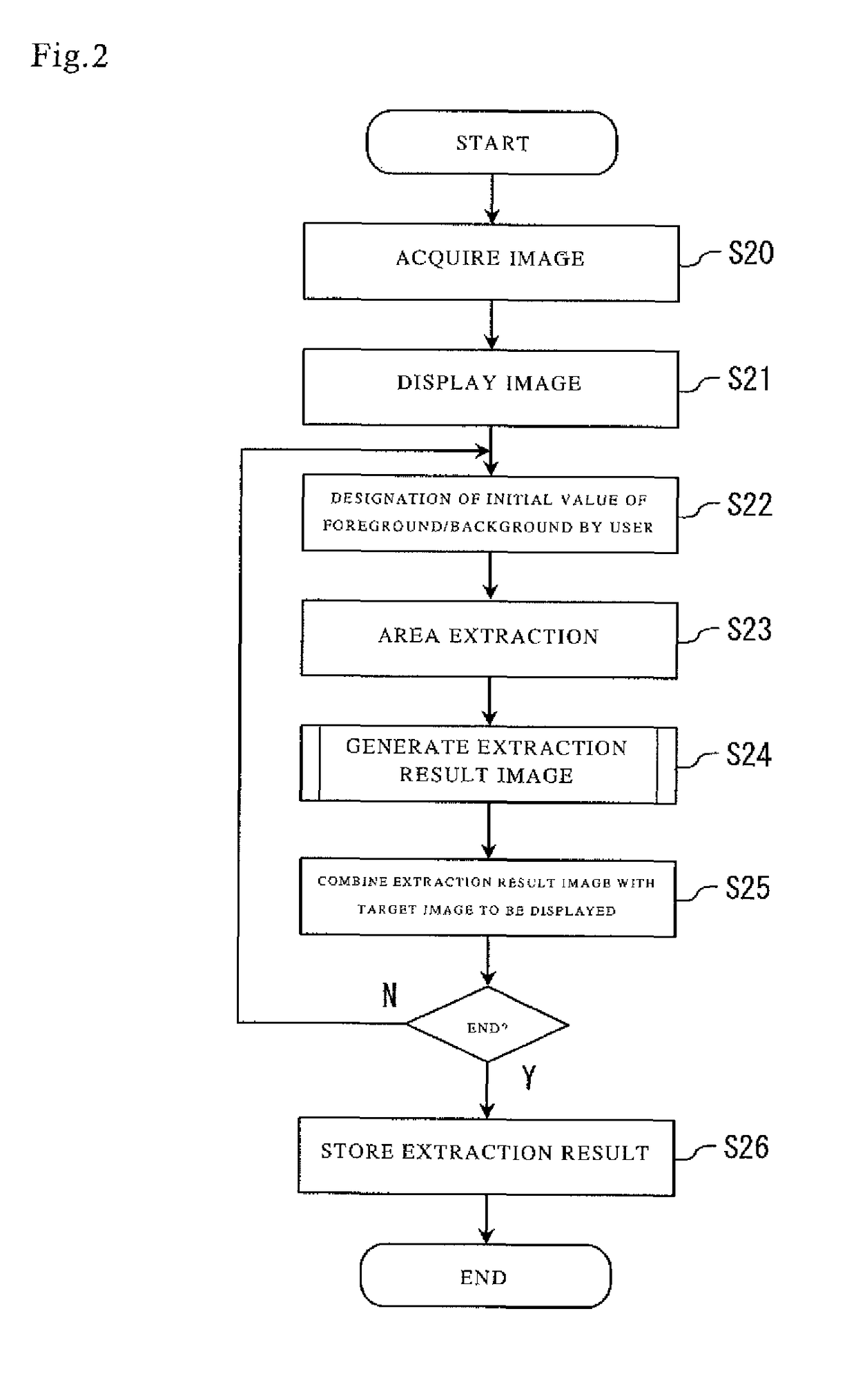
[0065]Next, a second embodiment of the present invention will be described. The second embodiment is different from the first embodiment, in which the displaying color is determined in such a manner as to have the largest sum of the absolute values of the color difference from the extracted color from the boundary peripheral area, in that the color most different from the extracted color from the boundary peripheral area in hue is selected as the displaying color. Specifically, only the content of the processing in Step S24 in the flow in FIG. 2 is replaced, and aside from this, the configuration and the processing are the same as those in the first embodiment.

[0066]FIGS. 7 and 8 show a method for displaying an extraction result in the second embodiment. FIG. 7 is a flowchart showing, in detail, the extraction result image generation processing shown in Step S24 in FIG. 2. FIG. 8 is a diagram for describing an algorithm for determining the displaying color of the extraction result i...

third embodiment

[0075]Next a third embodiment of the present invention will be described. In the first and the second embodiments, the filled area (estimated foreground area) is overlaid on the target image to be displayed. In addition, the contour line of the filled area is drawn in the third embodiment.

[0076]FIG. 9(a) shows a display example of extraction result image including the filled area provided with the contour line. By thus drawing such a contour line 90, the boundary between the estimated foreground area and the estimated background area becomes clearer. This is particularly effective when the boundary between the estimated foreground area and the estimated background area has a complicated shape or is intricate.

[0077]Examples of a method for determining the drawing color of the contour line 90 include the followings.

[0078](1) The color that is the same as the filling color of the filled area 91 is used as the drawing color of the contour line 90, with the transmittance when combined wi...


PUM


Abstract

A method for displaying a result of area extraction processing of dividing a target image into a foreground area and a background area includes a result acquisition step of acquiring a result of the area extraction processing on the target image, an extraction result image generation step of acquiring an extraction result image representing an estimated foreground area or an estimated background area estimated by the area extraction processing or a boundary between the estimated foreground area and the estimated background area, based on the acquired result, and a display step of generating a composite image by combining the extraction result image with the target image, and displaying the composite image on a display device. The extraction result image generation step includes a color extraction step and a color determination step.

Description

BACKGROUND[0001]Technical Field[0002]The present invention relates to a technique for displaying a result, of an area extraction on an image, in an easily recognizable manner.[0003]Related Art[0004]Processing called area extraction (segmentation) is one type of digital image processing performed by a computer. The area extraction processing is processing of dividing a target image into a foreground (portion to be extracted) and a background (other portions), based on image features such as colors and edge. The processing is used for a purpose of extracting a portion of an object or a person as a target of image processing or image recognition, for example.[0005]Various algorithms for the area extraction processing have been proposed, and the extraction accuracy of the area extraction processing has improved. However, there is no guarantee that only a portion, intended by a user, is extracted without fail by performing the processing only once. Therefore, most systems have a function...

Claims


Application Information

Patent Timeline
Patent Type & Authority Patents(United States)
IPC IPC(8): H04N1/56G06T11/00G06T7/12G06T7/194G06T11/60G09G5/02
CPCG09G5/024G06T7/12G06T7/194G06T11/001G06T11/60H04N1/56G09G5/026G09G2340/12G06T2207/10024G06T2207/20104G06T2207/20221G09G2320/0666
Inventor MINATO, YOSHIHISAYANAGAWA, YUKIKO
Owner ORMON CORP
Why Eureka
Try Eureka