Eureka AIR delivers breakthrough ideas for toughest innovation challenges, trusted by R&D personnel around the world.

Efficient lens re-distortion

a technology of redistortion and efficient lens, applied in image enhancement, image analysis, instruments, etc., can solve the problems of large amount of computational resources and the need to re-distort input images, and achieve the effect of quick and efficient generation

Inactive Publication Date: 2017-11-14
LUCASFILM ENTERTAINMENT
View PDF6 Cites 2 Cited by
  • Summary
  • Abstract
  • Description
  • Claims
  • Application Information

AI Technical Summary

Benefits of technology

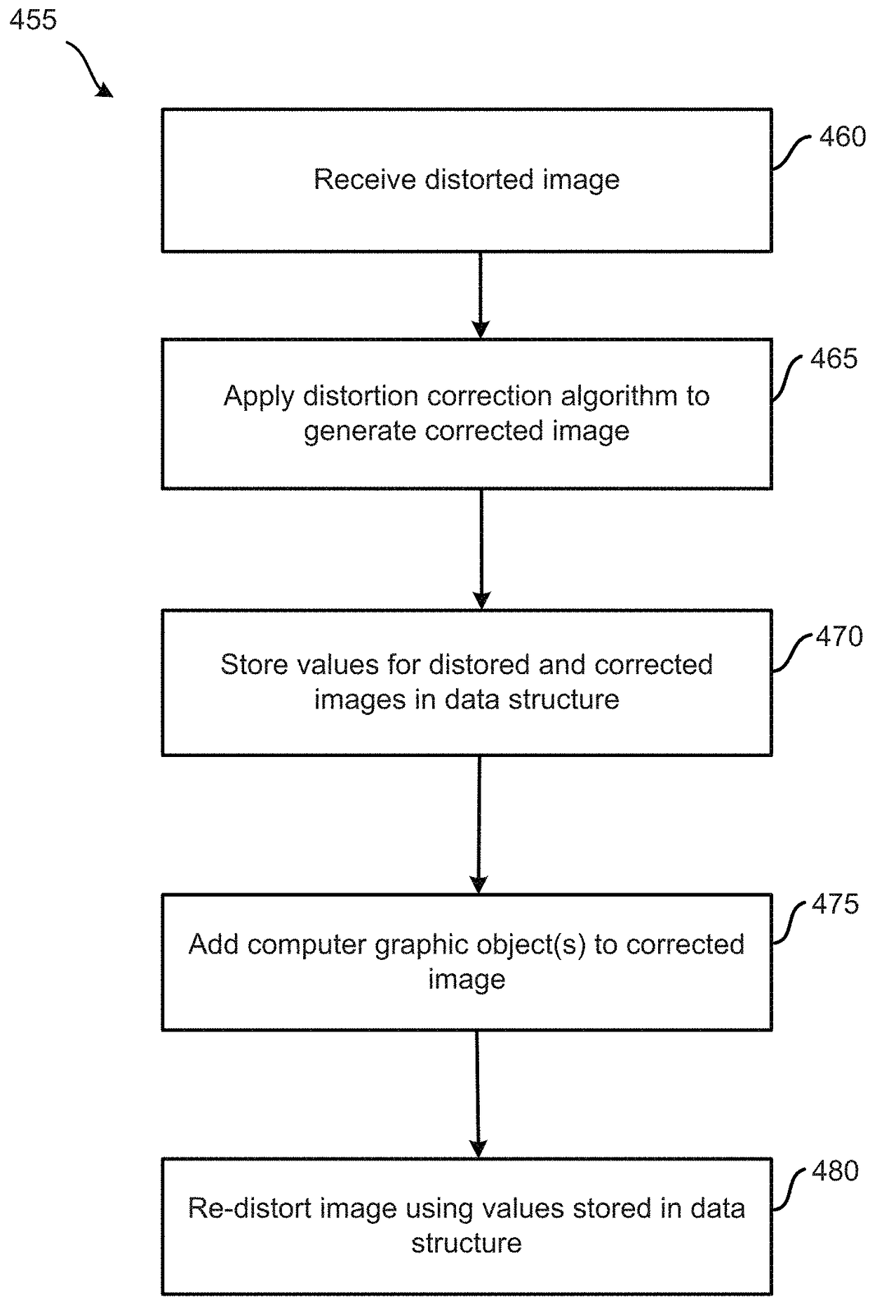
[0007]Embodiments enable a distorted image to be quickly and efficiently generated from a previously corrected image. Specifically, embodiments store or cache the distorted quadtree and quadtree decomposition generated during an initial correction of an input image. When re-distortion or inversion of the corrected input image is required, embodiments use the stored or cached distorted quadtree and quadtree decomposition to re-distort the image rather than calculating an associated inverse distortion function, which can require a large amount of computational resources.
[0011]Embodiments enable a distorted image to be quickly and efficiently generated from a source image, such as a previously corrected image. Specifically, some embodiments may store or cache a distorted quadtree and quadtree decompositions. When re-distortion or inversion of the corrected source image is required, embodiments use the stored or cached distorted quadtree and quadtree decomposition to re-distort the image rather than calculating an exact inverse of the distortion function, which can require a large amount of computational resources.

Problems solved by technology

Specifically, at a later time following any processing of the corrected input image, the corrected input image may have to be re-distorted.
When re-distortion or inversion of the corrected input image is required, embodiments use the stored or cached distorted quadtree and quadtree decomposition to re-distort the image rather than calculating an associated inverse distortion function, which can require a large amount of computational resources.

Method used


Image

  • Efficient lens re-distortion
  • Efficient lens re-distortion
  • Efficient lens re-distortion

Examples


Embodiment Construction

I. Introduction

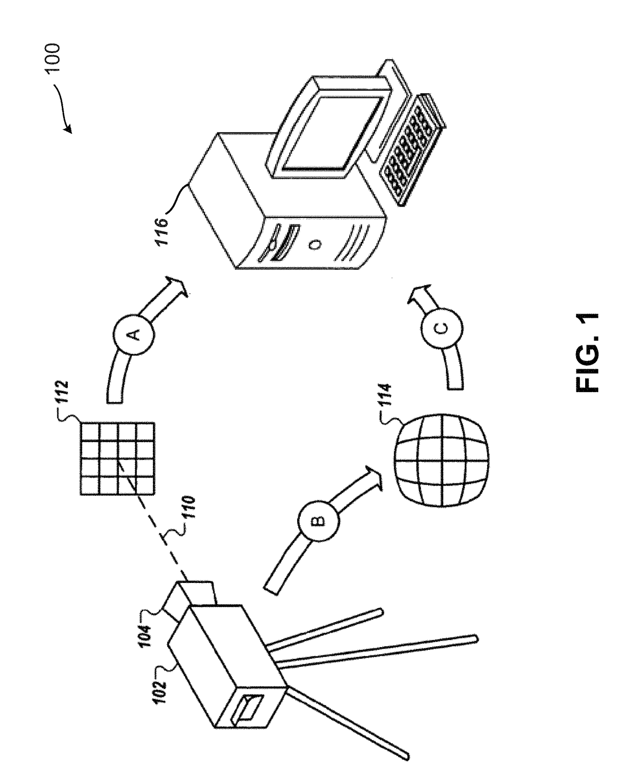
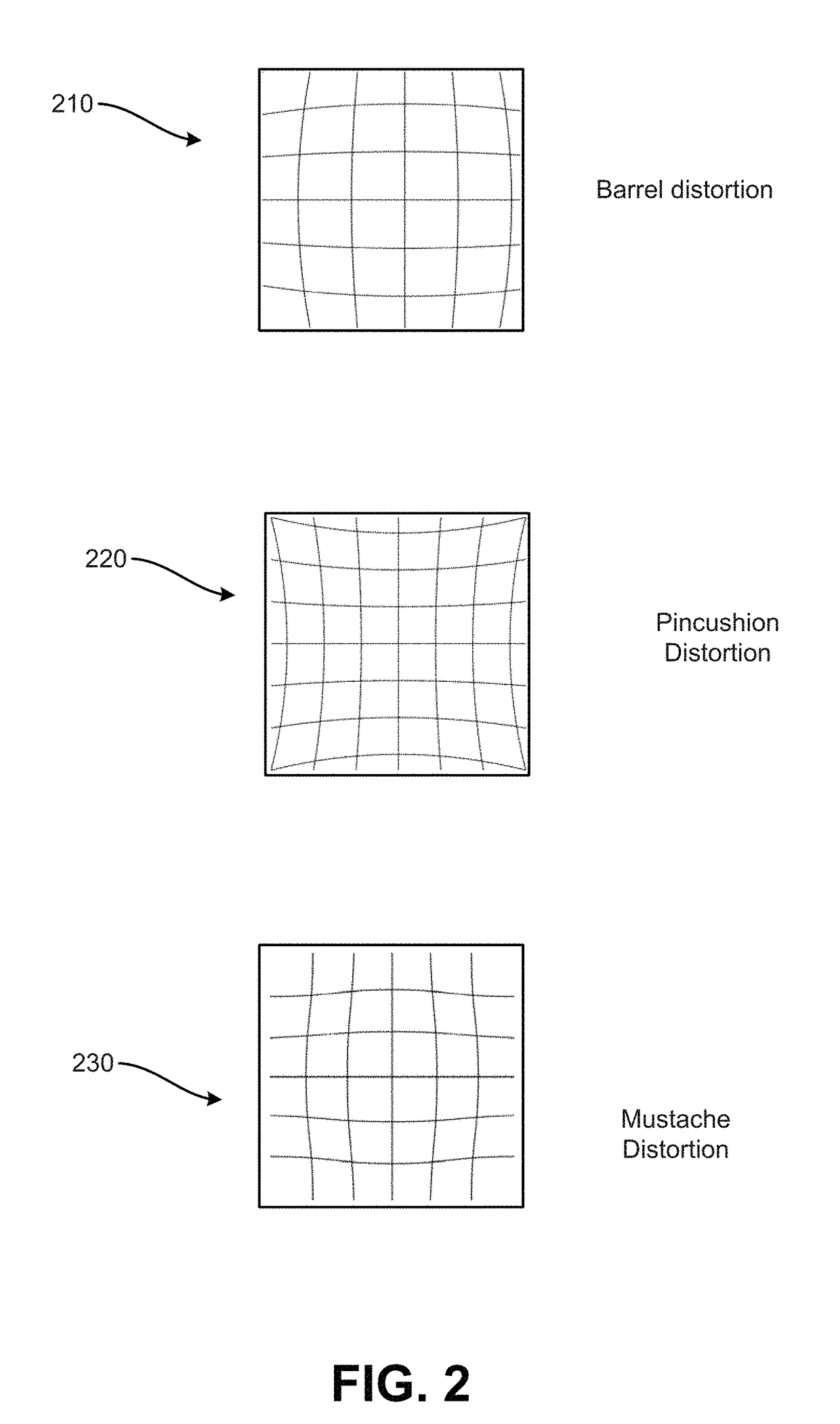
[0029]The following sections disclose exemplary embodiments for applying distortion to an image, such as when re-distorting or inverting, at least approximately, a previously corrected image. Section II gives information regarding image capture and the possible distortions that can arise. Additionally, methods for correcting such distortions are presented. Section III describes embodiments for applying distortion using a previously corrected source image to produce an output image by using a segmented rendered distortion image. Section IV describes additional and / or alternative embodiments for producing a segmented rendered distortion image and a quadtree data structure. Section V describes additional and / or alternative embodiments for applying a distortion. Section VI describes an exemplary computer system that may be used to implement the embodiments.

II. Origins of Image Distortion and Distortion Correction

[0030]FIG. 1 is a block diagram of an exemplary image proces...


PUM


Abstract

Methods and systems efficiently apply known distortion, such as of a camera and lens, to source image data to produce data of an output image with the distortion. In an embodiment, an output image field is segmented into regions so that on each segment the distortion function is approximately linear, and segmentation data is stored in a quadtree. The distortion function is applied to the segmented image field to produce a segmented rendered distortion image (SRDI) and a corresponding look-up table. To distort a source image, a location in the output image field is selected, and the uniquely colored segment at the same location in the SRDI is found. The look-up table provides the local linear inverse of the distortion function, which is applied to determine from where in the source image to take image texture data for the distorted output image.

Description

BACKGROUND[0001]Images, both still images and video images, are often referenced by a camera system and recorded in digital forms. Camera systems comprise at least one lens which focuses light from a physical scene onto an image plane, which for digital recording can be a planar array of light receptors in a charge coupled device (CCD). Image data recorded electronically (such as by a CCD) can be modified using various image processing techniques, for example, color filtering, edge detection, and noise removal.[0002]Lenses of the cameras in the aforementioned camera systems often cause distortions from what would be recorded by an ideal pinhole camera. In the ideal pinhole camera, a point on an object in the physical scene has a corresponding image point on an image plane such that the object point, the pinhole point and the corresponding image point all lie on the same line in a three-dimensional space. Actual lenses will typically not achieve the ideal due, for example, to their f...

Claims


Application Information

Patent Timeline
Patent Type & Authority Patents(United States)
IPC IPC(8): G06T5/00G06T3/00G06T7/00
CPCG06T3/0018G06T7/13G06T5/006G06T2207/20021H04N5/2628H04N23/81
Inventor MALLET, RONALD
Owner LUCASFILM ENTERTAINMENT
Why Eureka
Eureka Blog
Learn More