Hydrogen generation device and fuel cell system including same

a fuel cell and hydrogen generation technology, applied in the direction of cell components, sustainable manufacturing/processing, instruments, etc., can solve the problems of large amount of energy expended, difficult control of storage, adsorption, and loss of liquefied hydrogen, etc., to achieve rapid and efficient generation, quick start, and rapid start

Inactive Publication Date: 2011-01-11
TOYOTA JIDOSHA KK
View PDF23 Cites 0 Cited by
  • Summary
  • Abstract
  • Description
  • Claims
  • Application Information

AI Technical Summary

Benefits of technology

[0012]In view of the above, the invention provides a hydrogen generation device where a reforming reaction for generating hydrogen can be quickly started, and the required amount of hydrogen can be quickly and efficiently generated by the reforming reaction, for example, in the case where the hydrogen generation device is started when the temperature of a catalyst is lower than the temperature at which the reforming reaction can be carried out. The invention also provides a fuel cell system where a reforming reaction can be quickly started, and the required amount of electric power can be stably generated, for example, in the case where the fuel cell system is started when the temperature of a catalyst is lower than the temperature at which the reforming reaction can be carried out.
[0013]A steam-reforming reaction to generate hydrogen and a recovery reaction may be carried out alternately. The steam-reforming reaction is an endothermic reaction. The recovery reaction is an exothermic reaction. Thus, the recovery reaction raises the temperature of the catalyst, while the steam-reforming reaction lowers the temperature of the catalyst. Thus, by carrying out the recovery reaction alternately with the reforming reaction, it is possible to maintain the efficiency of the catalyst in generating hydrogen. In this case, the speed at which hydrogen is generated by the reforming reaction, that is, the speed at which the catalyst is brought to the reaction temperature needs to be increased before ordinary operation of a hydrogen generation device starts, for example, when the hydrogen generation device is started. The speed at which hydrogen is generated (heating speed of the catalyst) can be effectively improved by providing a plurality of reformers that have different heat efficiencies, for example, different heat capacities. In each of the reformers, the reforming reaction and the recovery reaction are carried out alternately. In view of this, the invention is made. The exothermic reaction according to the invention includes a combustion reaction.

Problems solved by technology

When liquefied hydrogen is stored as described in (ii), a portion of the liquefied hydrogen is lost due to vaporization, and a great amount of energy is expended in liquefying hydrogen.
Further, controlling storage, adsorption, and the like of hydrogen is difficult.
Providing an electric heater or the like as the heat source in the system decreases the energy efficiency of the entire system.
Currently, a method for supplying hydrogen has not been technically established.
As a result, much time is required to bring the temperatures of all the catalysts to the appropriate temperature for generating the amount of hydrogen that is needed.
That is, the reforming device cannot be activated in a short time.
When the amount of hydrogen needed sharply increases due to a sharp increase in the demand for electric power, for example, when the load on the HMFC 30 increases while the fuel cell is generating electric power, the reforming device cannot generate the additional hydrogen required immediately.
The power storage device is needed because the amount of hydrogen gas that is generated by the reforming device and supplied to the fuel cell is initially insufficient to generate the electric power required.
However, the additional components not only increase the weight of the fuel cell system, but the cost of the system as well.
Also, it is difficult to supply electric power stably using the large-sized electric power storage device.
Further, the large-sized electric power storage device occupies a large space in the vehicle.

Method used


Image

  • Hydrogen generation device and fuel cell system including same
  • Hydrogen generation device and fuel cell system including same
  • Hydrogen generation device and fuel cell system including same

Examples


first embodiment

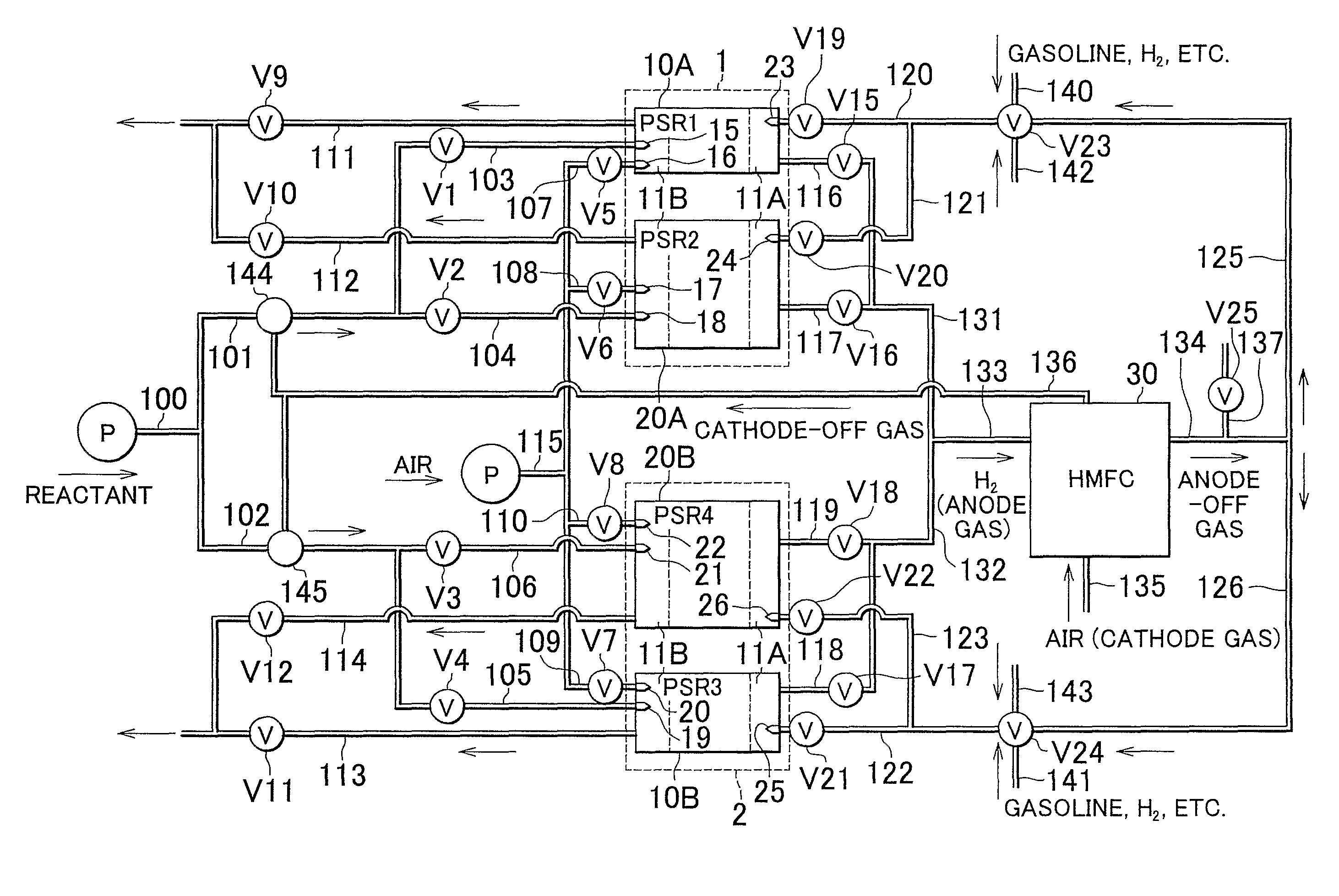
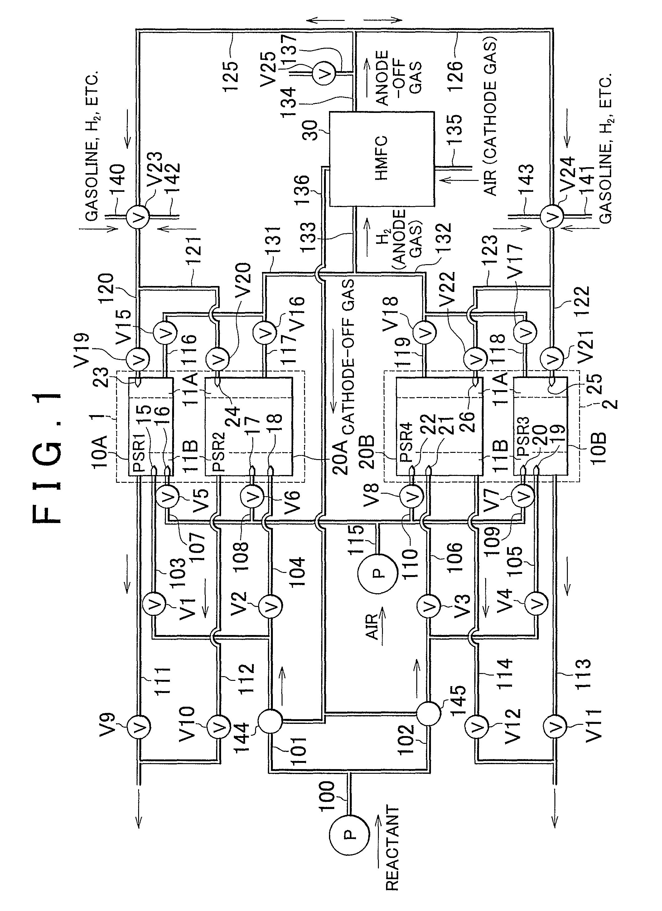
[0049]A fuel cell system according to the invention will be described with reference to FIG. 1 to FIG. 5. The fuel cell system according to the embodiment is provided in an electric vehicle. The fuel cell system includes a hydrogen membrane fuel cell (hereinafter, referred to as “HMFC”) and a hydrogen generation device according to the invention. The HMFC includes an electrolyte membrane where proton-conductive ceramic is provided on the surface of a hydrogen-permeable metal membrane. The hydrogen generation device includes reformers that have different heat capacities. When the fuel cell system is started, the temperature of the catalyst is raised to the temperature at which the reforming reaction can be carried out (hereinafter, referred to as “reforming-start temperature”). The reformers that have the smaller heat capacity will reach the reforming-start temperature more quickly than the reformers that have the greater heat capacity. As a result, the reforming reaction is preferen...

third embodiment

[0135]A fuel cell system according to the invention will be described with reference to FIG. 7. In this embodiment, the PSR reformers where the reforming reaction should be started are selected based on the values detected by the temperature sensors when the fuel cell system is started, irrespective of the known heat capacities of the PSR reformers, and the reforming reaction is started in the selected PSR reformers.

[0136]The reactant and the exothermic material that are used in the first embodiment can be used also in the third embodiment. The same and corresponding components as those in the first embodiment will be denoted by the same reference numerals, and detailed description thereof will be omitted.

[0137]In this embodiment, when the ignition switch is turned on, the catalyst temperatures (t1, t2, t3, and t4) in all the four PSR reformers are detected, and the PSR reformers where the catalyst temperature has reached the reforming-start temperature quickly are preferentially se...


PUM

PropertyMeasurementUnit
operating temperatureaaaaaaaaaa
diameteraaaaaaaaaa
temperatureaaaaaaaaaa

Abstract

In a hydrogen generation device according to the invention, PSR reformers have a heat capacity smaller than that of the other PSR reformers. Therefore, the temperature of the catalyst reaches to a reforming-start temperature more quickly in the PSR reformers than in the other PSR reformers. When the hydrogen generation device is started and the reforming reaction is carried out, the mixture of gasoline vapor and water vapor is selectively and preferentially supplied to the PSR reformers so that the reforming reaction is carried out in the PSR reformers.

Description

BACKGROUND OF THE INVENTION[0001]1. Field of the Invention[0002]The invention relates to a hydrogen generation device that alternately generates hydrogen through a reforming reaction using a catalyst, and recovers the catalyst via a recovery reaction. The recovery reaction recovers the catalyst by heating the catalyst for the next reforming reaction. The invention also relates to a fuel cell system that includes the hydrogen generation device.[0003]2. Description of the Related Art[0004]In electric vehicles, a fuel cell is provided as a power source. Hydrogen used to generate electric power in the fuel cell, or reactant used to generate hydrogen is provided.[0005]In the case where hydrogen itself is provided, it may be stored in the following ways: (i) the hydrogen gas is compressed, and stored in a high-pressure container, (ii) the hydrogen gas is liquefied and stored in a tank, or (iii) the hydrogen is provided using hydrogen storage alloy or hydrogen adsorbent. When hydrogen gas ...

Claims


Application Information

Patent Timeline
Patent Type & Authority Patents(United States)
IPC IPC(8): H01M10/50F01N3/20C01B3/02H01M8/00C01B3/38H01M8/02H01M8/04H01M8/06H01M8/10H01M8/12
CPCC01B3/38C01B3/46H01M4/94H01M8/04007H01M8/04223H01M8/04373H01M8/04753H01M8/04761H01M8/04776H01M8/0618H01M8/0662H01M8/1246H01M8/126C01B2203/0233C01B2203/0283C01B2203/0445C01B2203/047C01B2203/066C01B2203/0811C01B2203/0822C01B2203/0827C01B2203/1247H01M8/04268Y02E60/521Y02E60/525Y02E60/50Y02P20/10Y02P70/50H01M8/04302H01M8/04225H01M8/0258
Inventor MASUI, TAKATOSHIMITSUI, HIROYUKIAOKI, HIROSHISHIMAZU, TAKASHI
Owner TOYOTA JIDOSHA KK
Why Eureka
Try Eureka