

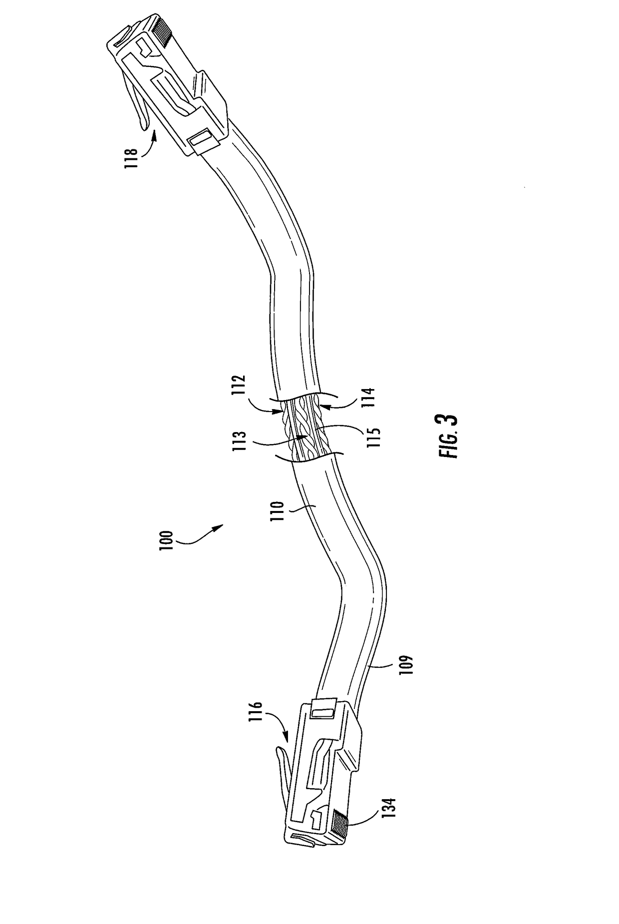
RJ-45 communication plug with plug blades received in apertures in a front edge of a printed circuit board
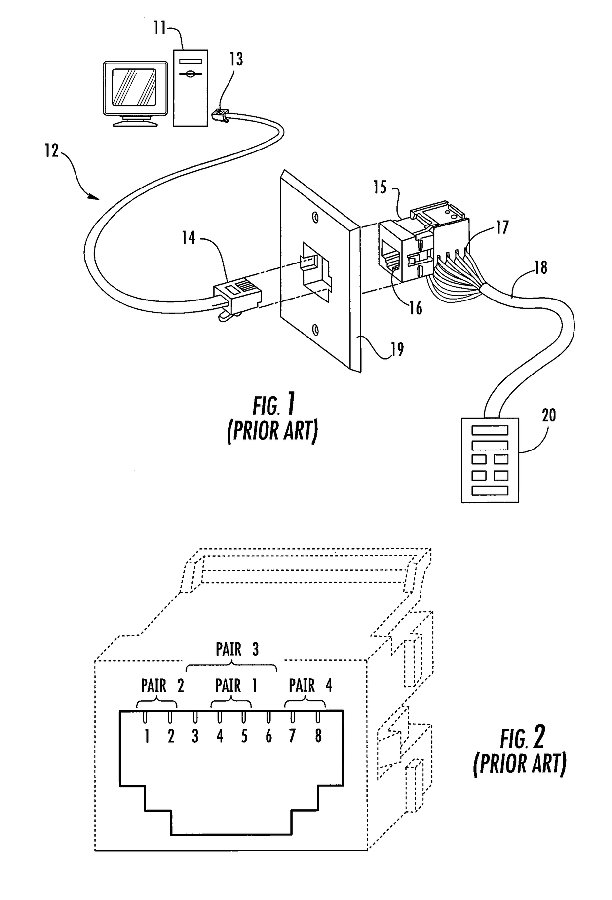
a communication plug and printed circuit board technology, applied in the field of module communication plugs, can solve the problems of degrading the quality of the signal carried by the conductor, causing a different type of noise, which is called “crosstalk”
- Summary
- Abstract
- Description
- Claims
- Application Information
AI Technical Summary
Benefits of technology
Problems solved by technology
Method used
Image

Examples
Embodiment Construction
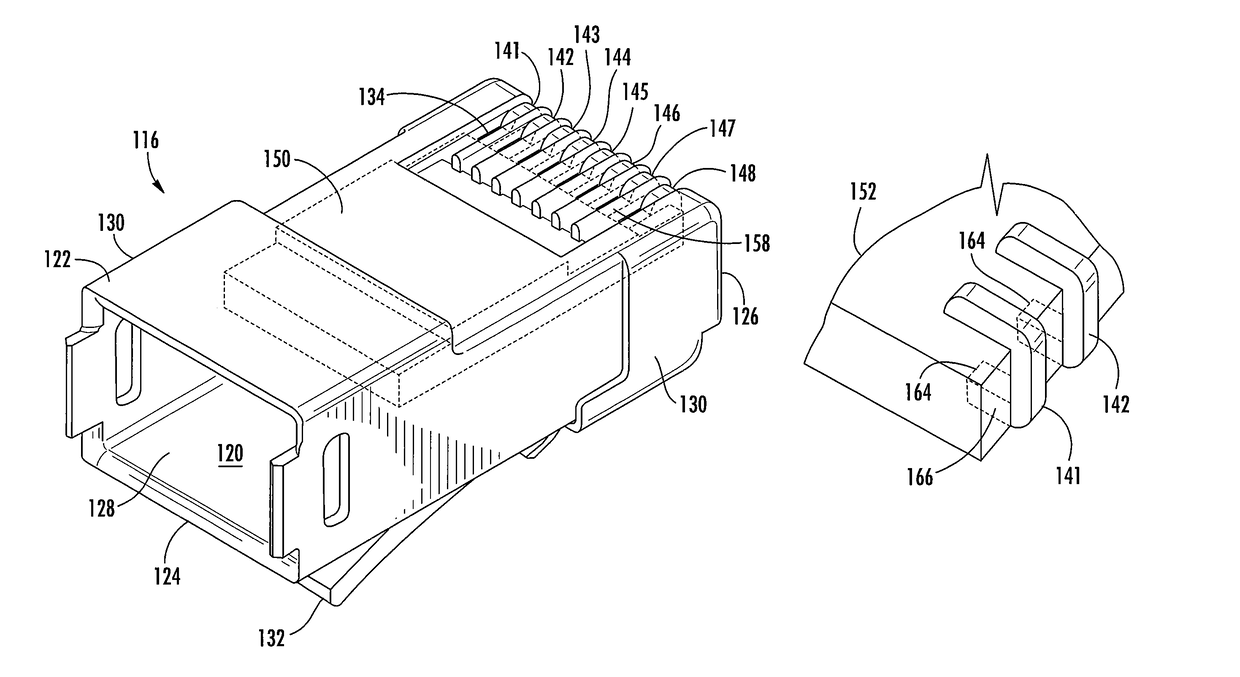
[0042]Pursuant to embodiments of the present invention, small form-factor modular communications plugs are provided that include low profile plug blades that are surface mounted on a printed circuit board. The communications plugs according to embodiments of the present invention may exhibit enhanced electrical performance (e.g., improved crosstalk performance, reduced return loss, etc.) and, in some embodiments, may be less expensive to manufacture.
[0043]The low profile plug blades may comprise, for example, metal strips or wires that are mounted on the top surface and front edge of the printed circuit board. In some embodiments, each plug blade may comprise a metal strip that is formed generally into an “L” shape, with the short side of the “L” extending vertically along the front edge of the printed circuit board and the longer side of the “L” extending along the top surface of the printed circuit board. In other embodiments, each plug blade may comprise a metal strip that is for...
PUM
| Property | Measurement | Unit |
|---|---|---|
| thickness | aaaaa | aaaaa |
| thickness | aaaaa | aaaaa |
| angle | aaaaa | aaaaa |
Abstract
Description
Claims
Application Information