Cutting tool for trimming workpiece

a cutting tool and workpiece technology, applied in the field of cutting tools, can solve the problems of inconvenient use of screw dies to trim damaged threads, become difficult,

Active Publication Date: 2017-11-21
SU CHENG WEI
View PDF13 Cites 11 Cited by
  • Summary
  • Abstract
  • Description
  • Claims
  • Application Information

AI Technical Summary

Benefits of technology

[0013]It is yet another objective of the present invention that the cutting tool neither unduly truncates the threaded fastener nor eliminates the numbers of threads.
[0014]It is yet another objective of the present invention that the cutting tool gets rid of trimmed pieces from the thread fastener easily and quickly.
[0015]It is yet another objective of the present invention that the cutting tool avoids the trouble of alignment as set forth.

Problems solved by technology

Generally, it is easy to engage a screw with a nut, but it becomes difficult if the screw is corroded, covered with dirt, or damaged.
Therefore, it is inconvenient to use a screw die to trim the damaged threads or to remove dirt from the screw.

Method used


Image

  • Cutting tool for trimming workpiece
  • Cutting tool for trimming workpiece
  • Cutting tool for trimming workpiece

Examples


Embodiment Construction

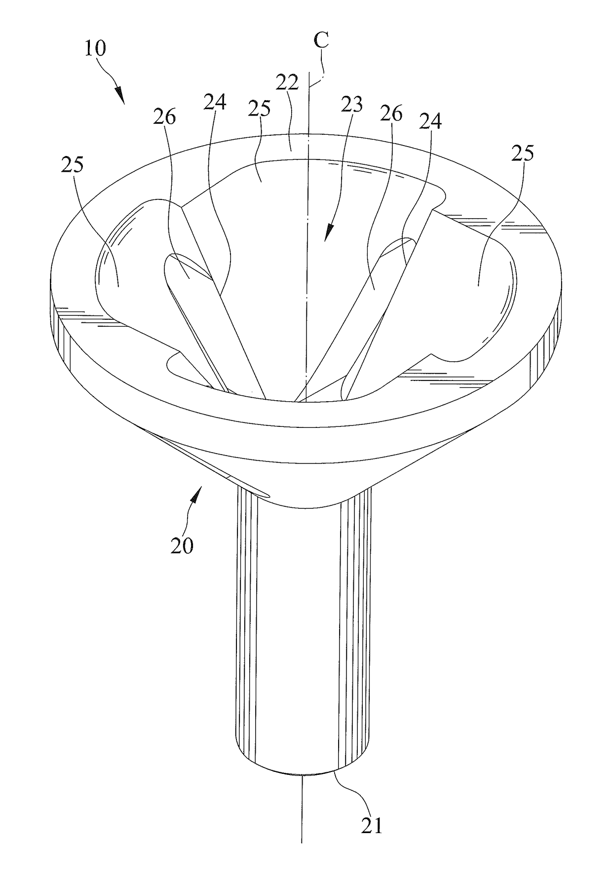
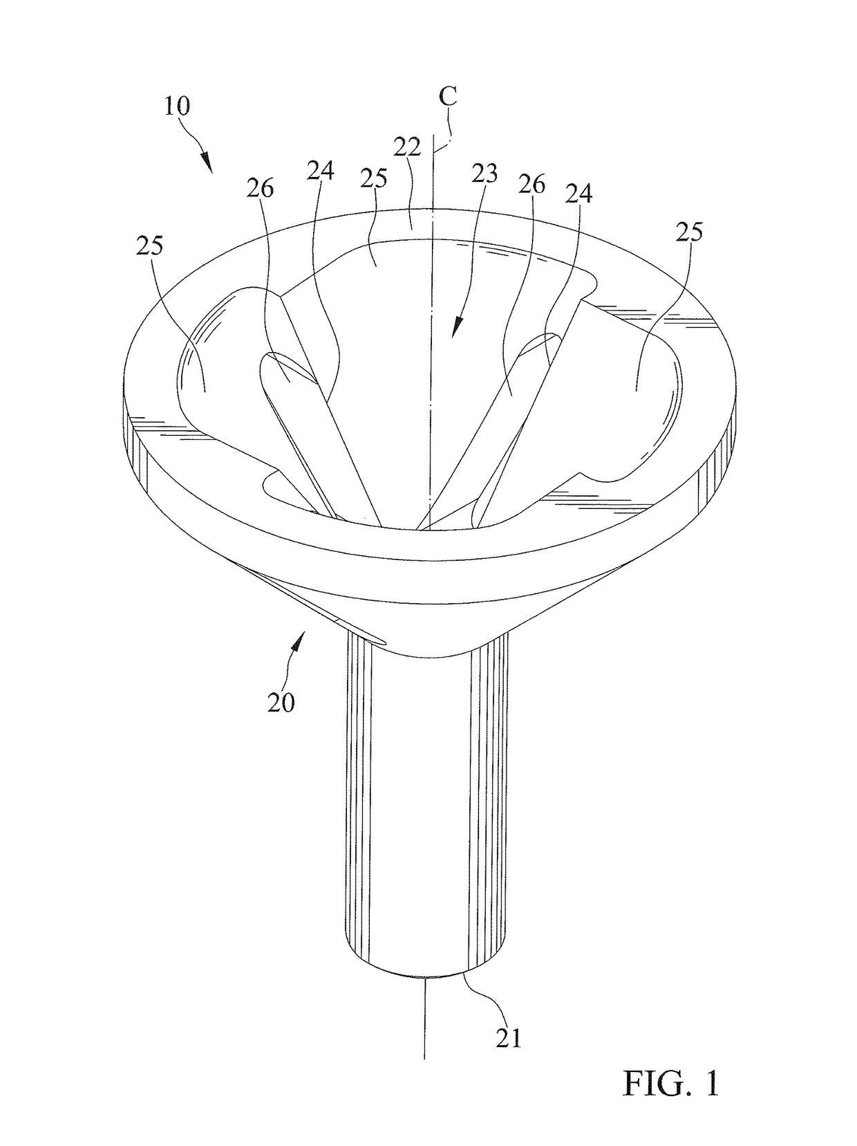
[0022]FIGS. 1 through 5 show a cutting tool 10 in accordance with the present invention. The cutting tool 10 is adapted to rotate relative to a workpiece and to trim the work piece.

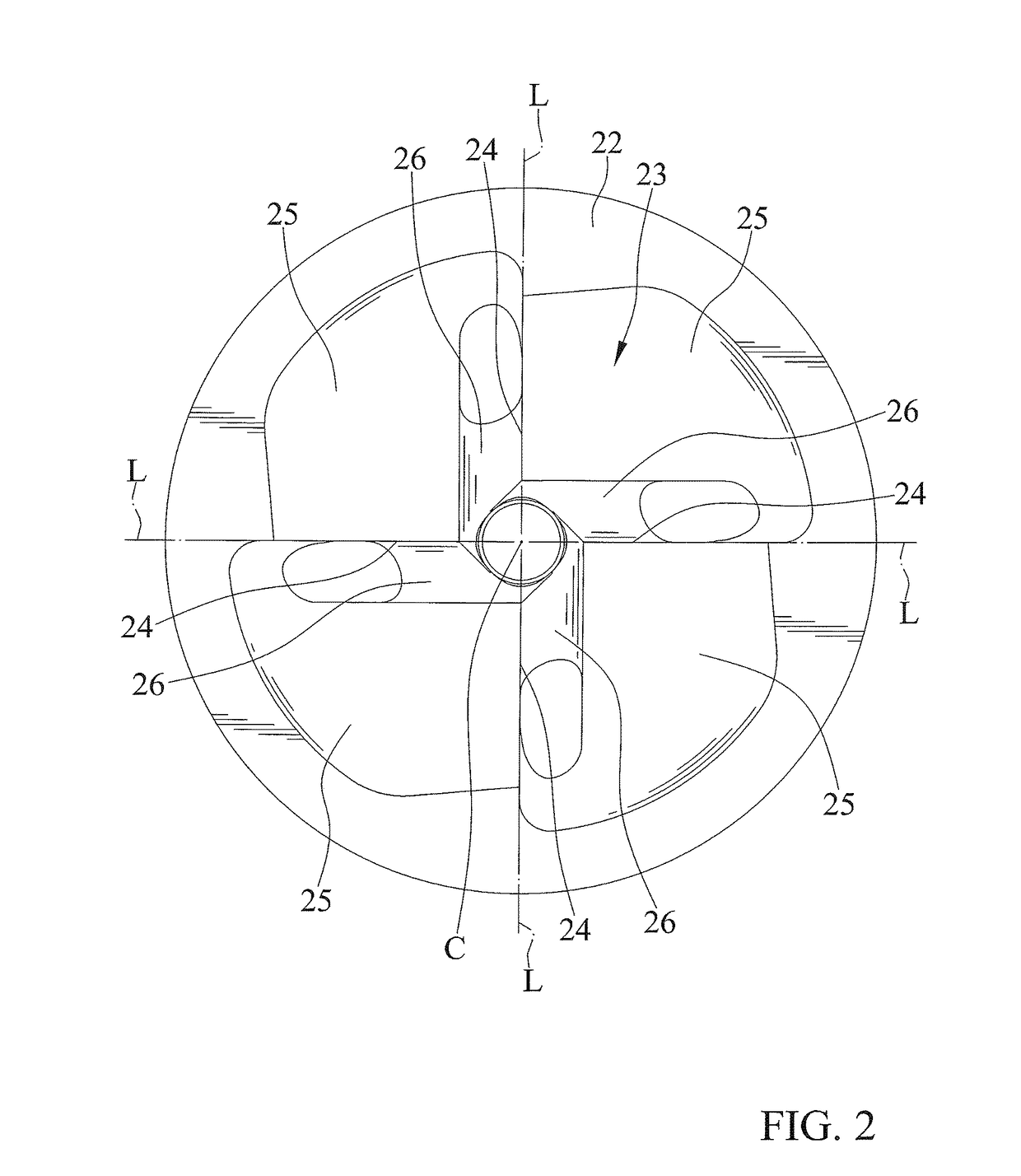
[0023]The cutting tool 10 includes a body 20 including a connecting end 21 at a first end for engaging with a driving tool 90, and a cutting end 22 at a second end and which includes a space 23 for receiving the work piece, at least one projection with a ridge defining at least one cutting edge 24 for cutting the work piece, and at least one slot 26 for allowing pieces trimmed from the workpiece to exit from the body 20. The body 20 is a one-piece structure.

[0024]The cutting end 22 has an annular inner periphery and an annular outer periphery. The inner periphery delimits the space 23 and defines the at least one projection and the at least one slot 26. In the embodiment, the cutting end 22 includes a plurality of cutting edges 24 and a plurality of slots 26. The space 23 has a top and a bottom and tapers...


PUM

PropertyMeasurementUnit
angleaaaaaaaaaa
angleaaaaaaaaaa
radial distanceaaaaaaaaaa

Abstract

A cutting tool includes a body including a connecting end, a cutting end which includes a space for receiving the work piece, at least one projection with a ridge defining at least one cutting edge for cutting the work piece, and at least one slot for allowing pieces trimmed from the workpiece to exit from the body. The space has a top and a bottom and tapers outwardly from the top to the bottom. The at least one cutting edge has a first end adjacent to the top of the space and a second end adjacent to the bottom of the space and extends from the first end to the second end obliquely. The body is rotatable about a first axis, and the first axis extends longitudinally between the first and second ends of the body.

Description

BACKGROUND OF THE INVENTION[0001]1. Field of the Invention[0002]The present invention relates to a cutting tool and, particularly, to a cutting tool adapted to rotate relative to a workpiece and to trim the workpiece.[0003]2. Description of the Related Art[0004]Generally, it is easy to engage a screw with a nut, but it becomes difficult if the screw is corroded, covered with dirt, or damaged. So, a screw die, which can create threads, is commonly used to trim damaged threads or to remove dirt from the screw. However, when using such screw die, it needs to be careful to avoid cutting threads which do not suffer the set forth problems. Therefore, it is inconvenient to use a screw die to trim the damaged threads or to remove dirt from the screw.[0005]The present invention is, therefore, intended to obviate or at least alleviate the problems encountered in the prior art.SUMMARY OF THE INVENTION[0006]According to the present invention, a cutting tool includes a body including a connectin...

Claims


Application Information

Patent Timeline
Patent Type & Authority Patents(United States)
IPC IPC(8): B23B5/16B23G9/00
CPCB23G9/003B23B5/167Y10T408/899Y10T408/893B23G2240/08
Inventor SU, CHENG-WEI
Owner SU CHENG WEI
Why Eureka
Try Eureka