Evaporator fan with shroud assembly

Inactive Publication Date: 2008-04-17
SUB-ZERO
6 Cites 10 Cited by

AI-Extracted Technical Summary

Problems solved by technology

Additionally, the greater the number of parts, the greater the potent...

Method used

[0028]Increasing the number of legs supporting the actuator reduces the perceived noise that is caused by the fan because the frequency of the noise created by the fan is determined by the number of legs on the shroud. A larger number of legs creates a higher frequency noise which is n...

Benefits of technology

[0003]Exemplary embodiments provide a fan assembly having a reduced noise level and a reduced assembly time. The fan assembly reduces the number of parts in the assembly by manufacturing the shroud from plastic and...

Abstract

A shroud for mounting a fan is provided. The shroud may include a plate, a hub, a first leg, and a second leg. The plate may include an aperture edge of an aperture in a surface of the plate. The hub includes a bore defining an axis of rotation of a fan. The first leg and the second leg are mounted to and extend between the hub and the aperture edge. The first leg includes a first leg portion having a first curve shape in a plane perpendicular to the axis of rotation. The second leg may include a second leg portion having a second curve shape in the plane. The first curve shape may be an arc of a circle. A fan housing may include the shroud, an actuator to effect rotation of the fan, and a mounting bracket, which mounts the actuator to the shroud.

Application Domain

Technology Topic

Image

  • Evaporator fan with shroud assembly
  • Evaporator fan with shroud assembly
  • Evaporator fan with shroud assembly

Examples

  • Experimental program(1)

Example

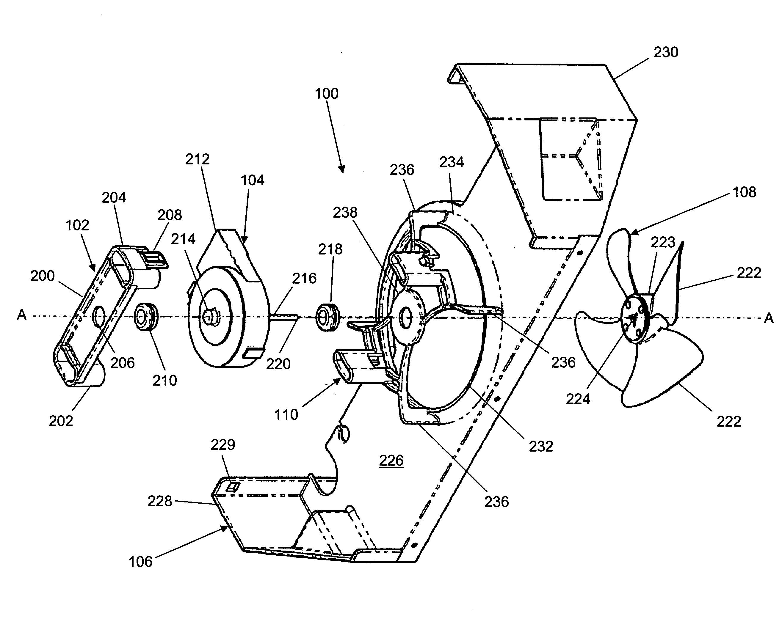
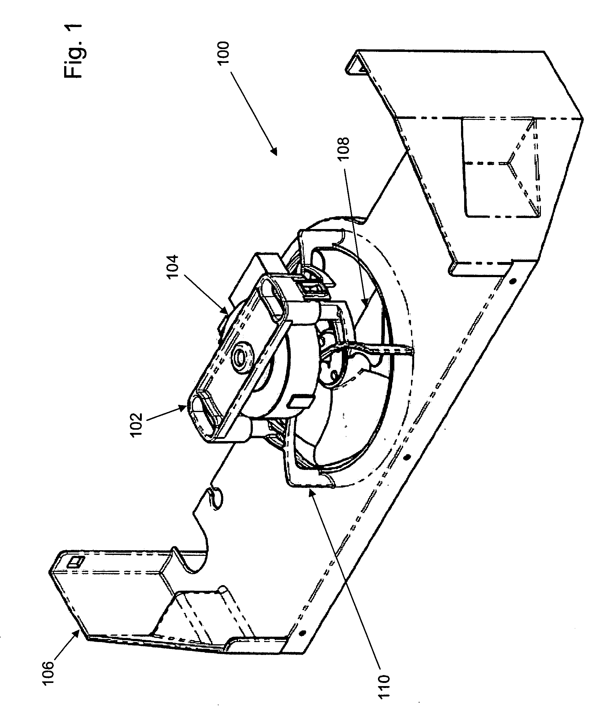
[0014]With reference to FIG. 1, a fan assembly 100 includes a mounting bracket 102, an actuator housing 104, a fan mounting frame 106, a fan 108, and a shroud 110. Fan assembly 100 may be mounted for use within a variety of devices. In an exemplary embodiment, fan assembly 100 is mounted adjacent a heat exchanger to circulate heated/cooled air. For example, fan assembly 100 may be mounted adjacent an evaporator in a refrigerator for circulation of cooled air. As used in this disclosure, the term “mount” includes join, unite, connect, associate, insert, hang, hold, affix, attach, fasten, bind, paste, secure, bolt, screw, rivet, solder, weld, and other like terms.
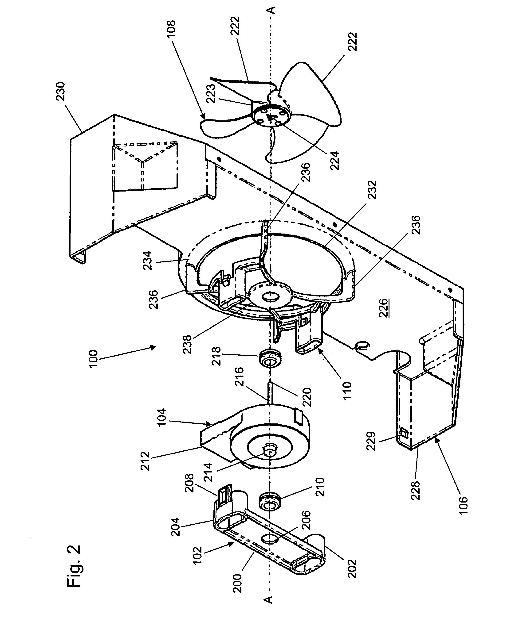
[0015]With reference to FIG. 2, an exploded view of fan assembly 100 is provided. Mounting bracket 102 may include a body 200, a first mounting arm 202, and a second mounting arm 204. First mounting arm 202 extends from a first end of body 200. Second mounting arm 204 extends from a second end of body 200 opposite the first end of body 200. Body 200 includes a bracket aperture edge 206 which defines an aperture for accepting an attachment mechanism such as a grommet or a nut. First mounting arm 202 may include a first clasp (not shown) extending from a side of first mounting arm 202. Second mounting arm 204 may include a second clasp 208 extending from a side of second mounting arm 204. Second clasp 208 may include a receptacle for accepting a latch.
[0016]With reference to FIG. 2, actuator housing 104 may include an actuator (not shown), a first attachment mechanism 210, a port 212, a mounting lug 214, an actuator shaft 216, and a second attachment mechanism 218. Actuator housing 104 mounts between mounting bracket 102 and shroud 110. The actuator is housed within actuator housing 104. The actuator may be any device as known to those skilled in the art both now and in the future for causing movement of fan 108. Exemplary actuators include an electric motor, a servo, stepper, or piezo motor, a pneumatic actuator, a gas motor, etc. Actuator housing 104 may have a variety of shapes and sizes to some extent dependent on the actuator selected. First attachment mechanism 210 may include a grommet or a nut as known to those skilled in the art both now and in the future. First attachment mechanism 210 isolates actuator housing 104 from mounting bracket 102 and positions actuator housing 104 correctly relative to mounting bracket 102. Second attachment mechanism 218 may include a grommet or a nut as known to those skilled in the art both now and in the future. Second attachment mechanism 218 isolates actuator housing 104 from shroud 110 and positions actuator housing 104 correctly relative to shroud 110.
[0017]Port 212 may accept a cable connecting the actuator with a power supply, pneumatic supply, and/or a controller. In the exemplary embodiment of FIG. 2, first attachment mechanism 210 fits over mounting lug 214. First attachment mechanism 210 mounts to bracket aperture edge 206 of mounting bracket 102 to mount actuator housing 104 to mounting bracket 102. In the exemplary embodiment of FIG. 2, actuator shaft 216 extends from actuator housing 104 in a direction and from a side of actuator housing 104 that is generally opposite mounting lug 214. Actuator shaft 216 extends through second mounting mechanism 218. Actuator shaft 216 includes a coupling end 220 that operably couples with fan 108.
[0018]With reference to FIG. 2, fan 108 may include a plurality of blades 222, a blade hub 223, and a shaft coupler 224. The plurality of blades 222 extend radially outward from blade hub 223. The plurality of blades 222 typically have an identical shape and are arranged symmetrically about blade hub 223. Shaft coupler 224 accepts coupling end 220 of actuator housing 104. The actuator effects rotation of actuator shaft 216. Through the coupling with shaft coupler 224, the rotational motion of actuator shaft 216 effects rotation of the plurality of blades 222. Thus, actuator shaft 216 acts as a rotor of fan 108. Actuator shaft 216 defines an axis of rotation A-A of the plurality of blades 222 of fan 108. In the exemplary embodiment of FIG. 2, the axis of rotation A-A extends through first and second attachment mechanisms 210, 218.
[0019]With reference to FIG. 2, fan mounting frame 106 may include a plate 226, a first wall 228, and a second wall 230. Plate 226 has a generally rectangular shape though other shapes, including square, circular, elliptical, polygonal, etc., and combinations of shapes may be used without limitation. In the exemplary embodiment of FIG. 2, plate 226 is sized and shaped to fit within an appropriately located space within a refrigerator or freezer to provide circulation of cooled air within the refrigerator or freezer. Plate 226 need not be a solid surface. For example, plate 226 may be formed of a mesh or a web of material. In the exemplary embodiment of FIG. 2, plate 226 extends in a plane that is generally perpendicular to axis A-A. First wall 228 and second wall 230 extend from plate 226 at generally opposed edges. First wall 228 may include a mounting aperture 229 in which an attachment mechanism such as a screw can be inserted for mounting fan mounting frame 106, for example, within the refrigerator or freezer. Second wall 230 further may include a mounting aperture (not shown).
[0020]Plate 226 further includes an aperture defined by an aperture edge 232. Aperture edge 232 may extend from an aperture wall 234 which extends from a generally planar surface of plate 226. Aperture edge 232 forms a generally circular shape though other shapes, including square, rectangular, elliptical, polygonal, etc., and combinations of shapes may be used without limitation. In the exemplary embodiment of FIG. 2, aperture edge 232 is sized and shaped to accommodate the plurality of blades 222 of fan 108 so that the plurality of blades 222 can rotate freely within the aperture.
[0021]Shroud 110 provides the structural foundation for fan assembly 100 and maintains the proper configuration between actuator housing 104 and fan 108. With reference to FIG. 2, shroud 110 may include a plurality of legs 236 and a hub 238. In the exemplary embodiment of FIG. 2, hub 238 includes a bore through which axis A-A extends. Second attachment mechanism 218 mounts to the bore of hub 238. The plurality of legs 236 support hub 238 over the aperture defined by aperture edge 232 and accommodate rotation of the plurality of blades 222 of fan 108.
[0022]With reference to FIG. 3, a perspective view of shroud 110 is provided with additional detail. With reference to FIG. 4, a top view of shroud 110 is provided. The plurality of legs 236 may include a first leg 300, a second leg 302, a third leg 304, and a fourth leg 306. First leg 300 may include a first leg portion 308 and a second leg portion 310. First leg portion 308 of first leg 300 mounts to and extends from aperture wall 234. In the exemplary embodiment of FIG. 3, first leg portion 308 of first leg 300 extends from aperture wall 234 in a direction that is generally perpendicular to plate 226 and parallel to axis A-A. In the exemplary embodiment of FIG. 3, second leg portion 310 of first leg 300 extends from first leg portion 308 of first leg 300 at a first end and mounts to hub 238 at a second end opposite the first end.
[0023]Second leg 302 may include a first leg portion 312 and a second leg portion 314. First leg portion 312 of second leg 302 mounts to and extends from aperture wall 234. In the exemplary embodiment of FIG. 3, first leg portion 312 of second leg 302 extends from aperture wall 234 in a direction that is generally perpendicular to plate 226 and parallel to axis A-A. In the exemplary embodiment of FIG. 3, second leg portion 314 of second leg 302 extends from first leg portion 312 of second leg 302 at a first end and mounts to hub 238 at a second end opposite the first end.
[0024]Third leg 304 may include a first leg portion 316 and a second leg portion 318. First leg portion 316 of third leg 304 mounts to and extends from aperture wall 234. In the exemplary embodiment of FIG. 3, first leg portion 316 of third leg 304 extends from aperture wall 234 in a direction that is generally perpendicular to plate 226 and parallel to axis A-A. In the exemplary embodiment of FIG. 3, second leg portion 318 of third leg 304 extends from first leg portion 316 of third leg 304 at a first end and mounts to hub 238 at a second end opposite the first end.
[0025]Fourth leg 306 may include a first leg portion 320 and a second leg portion 322. First leg portion 320 of fourth leg 306 mounts to and extends from aperture wall 234. In the exemplary embodiment of FIG. 3, first leg portion 320 of fourth leg 306 extends from aperture wall 234 in a direction that is generally perpendicular to plate 226 and parallel to axis A-A. In the exemplary embodiment of FIG. 3, second leg portion 322 of fourth leg 306 extends from first leg portion 320 of fourth leg 306 at a first end and mounts to hub 238 at a second end opposite the first end.
[0026]In the exemplary embodiment of FIG. 3, second leg portion 310 of first leg 300, second leg portion 314 of second leg 302, second leg portion 318 of third leg 304, and second leg portion 322 of fourth leg 306 generally extend in a plane perpendicular to axis A-A. As more clearly shown with reference to FIG. 4, second leg portion 310 of first leg 300, second leg portion 314 of second leg 302, second leg portion 318 of third leg 304, and second leg portion 322 of fourth leg 306 define curved shapes in the plane perpendicular to axis A-A. The view of FIG. 4 is in the plane perpendicular to axis A-A. As a result, axis A-A extends out of the page as shown in FIG. 4. With reference to FIG. 4, the curved shapes of second leg portion 318 of third leg 304 and of second leg portion 322 of fourth leg 306 may be arcs of a first circle 404. Similarly, the curved shapes of second leg portion 310 of first leg 300 and of second leg portion 314 of second leg 302 may be arcs of a second circle (not shown). The center of first circle 404 may be located outside of the aperture defined by aperture edge 232. The curved shapes of second leg portion 310 of first leg 300, of second leg portion 314 of second leg 302, of second leg portion 318 of third leg 304, and/or of second leg portion 322 of fourth leg 306 may be portions of a hyperbola, a parabola, an ellipse, a conic section, a quadratic curve, a free form curve, or any other mathematical function that defines a curve. As used in this disclosure, the term “curve” means a line or a surface that bends in a smooth continuous fashion.
[0027]In the exemplary embodiment of FIG. 3, first leg 300 is a mirror image of second leg 302 relative to a first plane parallel to axis A-A, and first leg 300 is a mirror image of fourth leg 306 relative to a second plane parallel to axis A-A. Additionally, third leg 304 is a mirror image of second leg 302 relative to the second plane, and third leg 304 is a mirror image of fourth leg 306 relative to the first plane.
[0028]Increasing the number of legs supporting the actuator reduces the perceived noise that is caused by the fan because the frequency of the noise created by the fan is determined by the number of legs on the shroud. A larger number of legs creates a higher frequency noise which is normally less noticeable to a consumer. By forming the legs with curves in the plane perpendicular to the axis of rotation of the plurality of blades 222 of fan 108, the amount of noise created by the fan is also reduced relative to that created using a conventional design for the legs.
[0029]In an exemplary embodiment, a first shroud leg may include first leg portion 308 of first leg 300, second leg portion 310 of first leg 300, second leg portion 314 of second leg 302, and first leg portion 312 of second leg 302 wherein second leg portion 310 of first leg 300 and second leg portion 314 of second leg 302 mount approximately tangentially to hub 238. A second shroud leg may include first leg portion 316 of third leg 304, second leg portion 318 of third leg 304, second leg portion 322 of fourth leg 306, and first leg portion 320 of fourth leg 306 wherein second leg portion 318 of third leg 304 and second leg portion 322 of fourth leg 306 mount approximately tangentially to hub 238. The first shroud leg may mount to hub 238 on a first side and the second shroud leg may mount to hub 238 on a second side, wherein the second side is generally opposite the first side.
[0030]In the exemplary embodiment of FIGS. 3 and 4, shroud 110 further includes a first mounting brace 324 and a second mounting brace 340. First mounting brace 324 may include a first receptacle 326, a first arm 332, a second arm 334, a third arm 336, a fourth arm 338, and a first latch 400 (shown with reference to FIG. 4). First receptacle 326 may include a first end 328 and a second end 330 opposite first end 328. First end 328 of first receptacle 326 defines an aperture sized and shaped to accept first mounting arm 202. First mounting arm 202 may fit over an exterior of first end 328 of first receptacle 326 or may fit within an interior of first end 328 of first receptacle 326. First latch 400 extends from a side of first receptacle 326 of first mounting brace 324. In an exemplary embodiment, first latch 400 includes a recess. As used in this disclosure, the term “recess” describes a variety of structural shapes including notch, cut, indentation, elbow, groove, corner, chamfer, slope, etc. that can provide a frictional or press fit with an edge of an object to be engaged. The first clasp of first mounting arm 202 engages with the recess of first latch 400 when first mounting arm 202 is mounted to first mounting brace 324 thereby mounting actuator housing 104 to shroud 110.
[0031]First arm 332 and second arm 334 of first mounting brace 324 extend between second leg portion 310 of first leg 300 and second end 330 of first receptacle 326 to support first receptacle 326. Third arm 336 and fourth arm 338 of first mounting brace 324 extend between second leg portion 322 of fourth leg 306 and second end 330 of first receptacle 326 to support first receptacle 326. Fewer or additional arms may be used to support first receptacle 326. In an alternative embodiment, second end 330 mounts directly to second leg portion 310 of first leg 300 and to second leg portion 322 of fourth leg 306. In another alternative embodiment, second end 330 of first receptacle 326 and/or first arm 332 and/or second arm 334 of first mounting brace 324 mount to first leg portion 308 of first leg 300. Similarly, second end 330 of first receptacle 326 and/or third arm 336 and/or fourth arm 338 of first mounting brace 324 mount to first leg portion 320 of fourth leg 306. First arm 332, second arm 334, third arm 336, and fourth arm 338 of first mounting brace 324 may define curved shapes in the plane perpendicular to axis A-A.
[0032]Second mounting brace 340 may include a second receptacle 342, a first arm 348, a second arm 350, a third arm 352, a fourth arm 402 (shown with reference to FIG. 4), and a second latch 354. Second receptacle 342 may include a first end 344 and a second end 346 opposite first end 344. First end 344 of second receptacle 342 defines an aperture sized and shaped to accept second mounting arm 204. Second mounting arm 204 may fit over an exterior of first end 344 of second receptacle 342 or may fit within an interior of first end 344 of second receptacle 342. Second latch 354 extends from a side of second receptacle 342 of second mounting brace 340. In an exemplary embodiment, second latch 354 includes a recess. Second clasp 208 of second mounting arm 204 engages the recess of second latch 354 when second mounting arm 204 is mounted to second mounting brace 340 thereby mounting actuator housing 104 to shroud 110.
[0033]First arm 348 and second arm 350 of second mounting brace 340 extend between second leg portion 314 of second leg 302 and second end 346 of second receptacle 342 to support second receptacle 342. Third arm 352 and fourth arm 402 of second mounting brace 340 extend between second leg portion 318 of third leg 304 and second end 346 of second receptacle 342 to support second receptacle 342. Fewer or additional arms may be used to support second receptacle 342. In an alternative embodiment, second end 346 of second receptacle 342 mounts directly to second leg portion 314 of second leg 302 and to second leg portion 318 of third leg 304. In another alternative embodiment, second end 346 of second receptacle 342 and/or first arm 348 and/or second arm 350 of second mounting brace 340 mount to first leg portion 312 of second leg 302. Similarly, second end 346 of second receptacle 342 and/or third arm 352 and/or fourth arm 402 of second mounting brace 340 mount to first leg portion 316 of third leg 304. First arm 348, second arm 350, third arm 352, and fourth arm 402 of second mounting brace 340 may define curved shapes in the plane perpendicular to axis A-A.
[0034]Shroud 110 may be formed of plastic or of metal. In an exemplary embodiment, shroud 110 and plate 226 are formed of a single piece of material. In another exemplary embodiment, shroud 110 and fan mounting frame 106 are formed of a single piece of material.
[0035]The foregoing description of exemplary embodiments of the invention have been presented for purposes of illustration and of description. It is not intended to be exhaustive or to limit the invention to the precise form disclosed, and modifications and variations are possible in light of the above teachings or may be acquired from practice of the invention. The embodiments were chosen and described in order to explain the principles of the invention and as practical applications of the invention to enable one skilled in the art to utilize the invention in various embodiments and with various modifications as suited to the particular use contemplated. It is intended that the scope of the invention be defined by the claims appended hereto and their equivalents.

PUM

no PUM

Description & Claims & Application Information

We can also present the details of the Description, Claims and Application information to help users get a comprehensive understanding of the technical details of the patent, such as background art, summary of invention, brief description of drawings, description of embodiments, and other original content. On the other hand, users can also determine the specific scope of protection of the technology through the list of claims; as well as understand the changes in the life cycle of the technology with the presentation of the patent timeline. Login to view more.

Similar technology patents

Apparatus and method for radiation detection

InactiveCN1433520AReduce noise levelIncrease signal levelCathode ray tubes/electron beam tubesSecondary-electron emitting electrode tubesRadiationIonizing radiation
Owner:XCOUNTER

Pneumatic tire

InactiveUS20070006952A1Reduce vibration noiseReduce noise levelTyre tread bands/patternsNon-skid devicesContact patchEngineering
Owner:TOYO TIRE & RUBBER CO LTD

Apparatus and method for reducing noise for moveable target

InactiveUS20070140060A1Reduce noise levelSound producing devicesDirection/deviation determination systemsEngineeringNoise level
Owner:CATERPILLAR INC

Classification and recommendation of technical efficacy words

  • Reduces assembly time
  • Reduce noise level

Thermally Tunable Laser with Single Solid Etalon Wavelength Locker

InactiveUS20060039421A1Reduces assembly timeCost reductionLaser detailsSemiconductor lasersTunable laserSemiconductor laser theory
Owner:HUANG RONG

Error proof anti-chucking wedge assembly

InactiveUS20050060867A1Reduces assembly timeImprove installation toleranceVehicle seatsBuilding locksEngineeringMechanical engineering
Owner:NEWFREY

Device for cooling charge air

ActiveUS20120017877A1Reduces assembly timeCost and weight advantageInternal combustion piston enginesIndirect heat exchangersExhaust gasEngineering
Owner:DR ING H C F PORSCHE AG

System and Method of Use for Composite Floor

InactiveUS20110113714A1Decrease costReduces assembly timeWallsFloorsFastenerEngineering
Owner:NEW JERSEY INSTITUTE OF TECHNOLOGY

Axial-flow fan

InactiveUS20070122271A1Increase amount of airflowReduce noise levelPump componentsStatorsImpellerAirflow
Owner:SANYO DENKI CO LTD
Why Eureka
Try Eureka