Low cost multiple pattern antenna for use with multiple receiver systems

a receiver system and low cost technology, applied in the direction of resonant antennas, individually energized antenna arrays, different interacting antenna combinations, etc., can solve the problems of low performance, large influence on performance, and poor corresponding antenna gains

Inactive Publication Date: 2005-05-17
IPR LICENSING INC
View PDF5 Cites 59 Cited by
  • Summary
  • Abstract
  • Description
  • Claims
  • Application Information

AI Technical Summary

Benefits of technology

[0005]This invention relates to an adaptive antenna array for a wireless communications application that optionally uses multiple receivers. The invention provides a low cost, compact antenna system that offers high performance with the added

Problems solved by technology

In fact, so much emphasis has been placed on obtaining small size for radio equipment that corresponding antenna gains are extremely poor.
Consequently, the receivers in such phones generally do not have the ability to mitigate interference or reduce fading.
The problem with this type of antenna system is that performance is heavily influenced by the spatial separation between the antenna elements.
If the antennas are too close together or if they are arranged in a sub-optimum geometry with respect to one another, then the performance o

Method used


Image

  • Low cost multiple pattern antenna for use with multiple receiver systems
  • Low cost multiple pattern antenna for use with multiple receiver systems
  • Low cost multiple pattern antenna for use with multiple receiver systems

Examples


Embodiment Construction

[0028]A description of preferred embodiments of the invention follows.

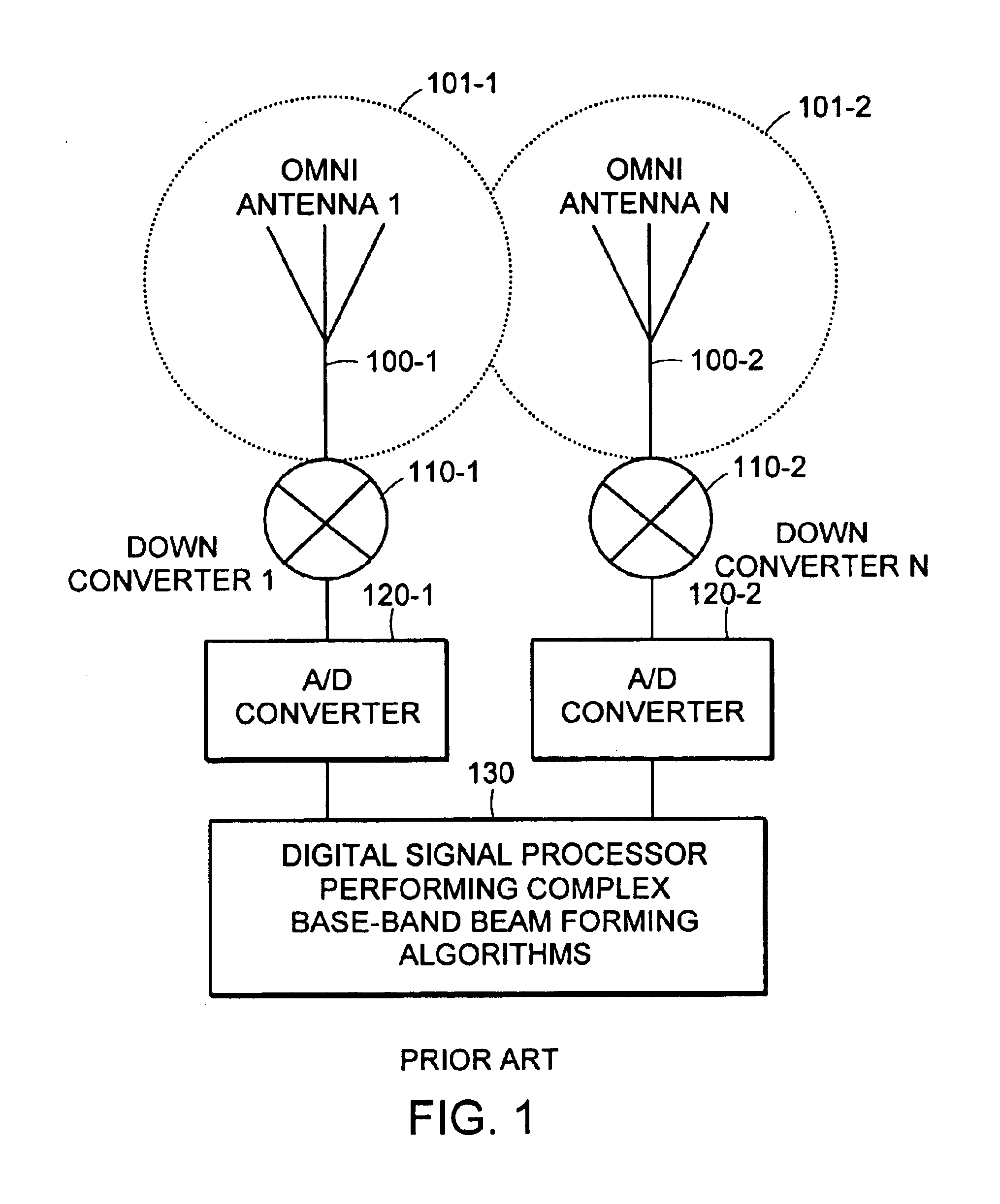
[0029]FIG. 1 illustrates prior art multiple element beam former. Such systems are characterized by having at least two active or radiating antenna elements 100-1, 100-2 that have associated omni-directional radiating patterns 101-1, 101-2, respectively. The antenna elements 100 are each connected to a corresponding radio receiver, such as down-converters 110-1 and 110-2, which provide baseband signals to a respective pair of Analog-to-Digital (A / D) converters 120-1, 120-2. The digital received signals are fed to a digital signal processor 130. The digital signal processor 130 then performs baseband beam forming algorithms, such as combining the signals received from the antenna elements 100 with complex magnitude and phase weighting functions.

[0030]One difficulty with this type of system is that performance is heavily influenced by the spatial separation and geometry of the antenna elements 100. For example, if th...


PUM


Abstract

An antenna assembly includes at least two active or main radiating omni-directional antenna elements arranged with at least one beam control or passive antenna element used as a reflector. The beam control antenna element(s) may have multiple reactance elements that can electrically terminate it to adjust the input or output beam pattern(s) produced by the combination of the active antenna elements and the beam control antenna element(s). More specifically, the beam control antenna element(s) may be coupled to different terminating reactances to change beam characteristics, such as the directivity and angular beamwidth. Processing may be employed to select which terminating reactance to use. Consequently, the radiator pattern of the antenna can be more easily directed towards a specific target receiver/transmitter, reduce signal-to-noise interference levels, and/or increase gain by using Radio Frequency (RF), Intermediate Frequency (IF), or baseband processing. A Multiple-Input, Multiple-Output (MIMO) processing technique may be employed to operate the antenna assembly with simultaneous beam patterns.

Description

RELATED APPLICATION(S)[0001]This application claims the benefit of U.S. Provisional Application No. 60 / 411,570, filed on Sep. 17, 2002. The entire teachings of the above application are incorporated herein by reference.BACKGROUND OF THE INVENTION[0002]It is becoming increasingly important to reduce the size of radio equipment to enhance its portability. For example, the smallest available cellular telephone handset today can conveniently fit into a shirt pocket or small purse. In fact, so much emphasis has been placed on obtaining small size for radio equipment that corresponding antenna gains are extremely poor. For example, antenna gains of the smallest handheld phones are only −3 dBi or even lower. Consequently, the receivers in such phones generally do not have the ability to mitigate interference or reduce fading.[0003]Some prior art systems provide multiple element beam formers for these purposes. These antenna systems are characterized by having at least two radiating element...

Claims


Application Information

Patent Timeline
IPC IPC(8): H01Q1/22H01Q9/04H01Q19/00H01Q19/32H01Q9/16H01Q21/29H01Q21/00H01Q3/26H01Q3/44H01Q19/26H01Q21/06H01Q21/08H01Q21/20
CPCH01Q1/22H01Q1/2258H01Q3/2641H01Q9/16H01Q21/29H01Q19/32H01Q21/08H01Q21/20H01Q19/26H01Q3/00H01Q3/28H01Q19/00H01Q21/00
Inventor CHIANG, BINGGAINEY, KENNETH M.PROCTOR, JR., JAMES A.ROUPHAEL, ANTOINE J.GOTHARD, GRIFFIN K.LYNCH, MICHAEL J.
Owner IPR LICENSING INC
Why Eureka
Try Eureka