Length-variable condensable annular separation device heat exchanger

A separation device and heat exchanger technology, applied in indirect heat exchangers, heat exchanger types, heat transfer modification, etc., can solve problems such as inability to stabilize flow, difficulty in entering and passing fluid, and affecting fluid heat transfer, etc. , to achieve the effect of reducing noise level, promoting smooth flow and enhancing heat transfer

Active Publication Date: 2017-07-21
SHANDONG UNIV
View PDF4 Cites 60 Cited by
  • Summary
  • Abstract
  • Description
  • Claims
  • Application Information

AI Technical Summary

Problems solved by technology

However, it was found during the operation of this device that the space A formed between the three pipes is relatively small because the pipes are tightly combined, because the space A is formed by the convex arc of the three pipes, so most of the space A The narrow space will make it difficult for the fluid to enter and pass through, resulting in a short circuit of the fluid, which affects the heat exchange of the fluid and cannot play a good role in stabilizing the flow
Simultaneously because the many tubes of above-mentioned structure are combined together, manufacture difficulty

Method used


Image

  • Length-variable condensable annular separation device heat exchanger
  • Length-variable condensable annular separation device heat exchanger
  • Length-variable condensable annular separation device heat exchanger

Examples


Embodiment Construction

[0040] The specific embodiments of the present invention will be described in detail below in conjunction with the accompanying drawings.

[0041] In this article, if there is no special explanation, when it comes to formulas, " / " means division, and "×" and "*" mean multiplication.

[0042] It should be noted that, unless otherwise specified, the two-phase flow mentioned in the present invention is a vapor-liquid two-phase flow, where the vapor phase can be condensed into a liquid phase during the heat exchange process.

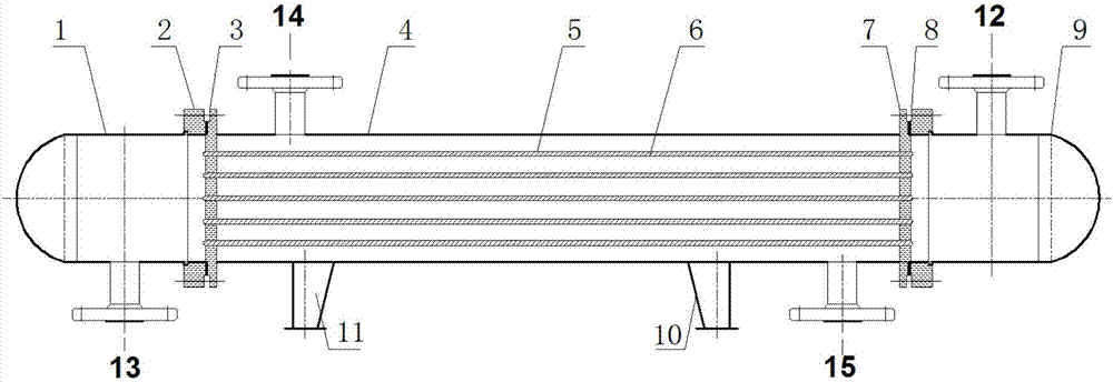
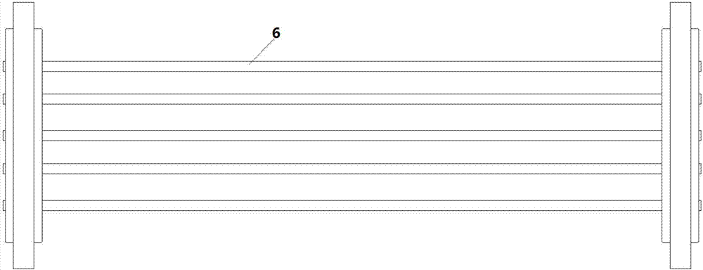
[0043] Such as figure 1 A shell-and-tube heat exchanger is shown, and the shell-and-tube heat exchanger includes a shell 4, a heat exchange tube 6, a tube-side inlet pipe 12, a tube-side outlet pipe 13, a shell-side inlet connecting pipe 14 and a shell The outlet connecting pipe 15; the heat exchange tube bundle composed of a plurality of parallel heat exchange tubes 6 is connected to the front tube sheet 3 and the rear tube sheet 7; the front end of the f...


PUM


Abstract

The invention provides a vapor-liquid two-phase flow tube shell type heat exchanger. The heat exchanger comprises a shell, wherein sealing heads are arranged at two ends of the shell respectively; tube plates are arranged in connection positions between the sealing heads and the shell; heat exchange tubes are connected with the tube plates at two ends; vapor phase in vapor-liquid two-phase flow can be condensed into liquid phase in the heat exchange process; the vapor-liquid two-phase flow flows in a tube process; separation devices used for decreasing vibration and reducing noise are arranged in the heat exchange tubes; a plurality of separation devices are arranged in the same heat exchange tube; the length of the separation devices is gradually reduced along the flowing direction of flow in the heat exchange tubes. According to the vapor-liquid two-phase flow tube shell type heat exchanger, the vibration of the tubes can be decreased to a maximum extent due to the length change of the separation devices when the vapor-liquid two-phase flow flows in the tubes; the noise level is reduced; meanwhile, the flowing resistance is reduced; the heat exchange uniformity is improved.

Description

technical field [0001] The present invention relates to a shell-and-tube heat exchanger, and more particularly to a two-phase flow heat exchanger containing condensable gas. Background technique [0002] Vapor-liquid two-phase flow heat exchange widely exists in various heat exchange devices. Due to the existence of the vapor phase in the heat exchange process of vapor-liquid two-phase flow, the heat exchange efficiency will be low, the heat exchange will be deteriorated, and the fluid flow process will be unstable. , and will lead to the occurrence of water hammer phenomenon. When the gas-liquid phase of the two-phase working fluid is not uniformly mixed and flows discontinuously, the large-sized liquid mass will occupy the air mass space at high speed, resulting in unstable two-phase flow, which will violently impact equipment and pipelines, resulting in strong vibration and noise , which seriously threatens the safety of equipment operation. [0003] The applicant has a...

Claims


Application Information

Patent Timeline
Patent Type & Authority Applications(China)
IPC IPC(8): F28D7/16F28F1/40F28F13/06
CPCF28D7/16F28F1/40F28F13/06
Inventor 范明秀张冠敏冷学礼田茂诚张莉莉柏超邱燕
Owner SHANDONG UNIV
Why Eureka
Try Eureka