Wind Powered System for Reducing Energy Consumption of a Primary Power Source

a technology of primary power source and wind power, which is applied in the direction of wind power generation, motors, couplings, etc., can solve the problems of increasing the cost of diesel fuel, affecting the reliability of the system, and the inability to establish connections in a robust and low maintenance manner, so as to reduce the energy consumption of a primary power source, reduce the load, and reduce the energy consumption of the primary power source.

Inactive Publication Date: 2012-04-19
HALL RONALD +2
View PDF2 Cites 9 Cited by
  • Summary
  • Abstract
  • Description
  • Claims
  • Application Information

AI Technical Summary

Benefits of technology

[0017]According to yet another aspect of the invention, there is provided a system for reducing energy consumption of a primary power source comprising: a wind powered apparatus comprising a wind turbine having a hydraulic drive system comprising a hydraulic pump powered by the wind turbine and a hydraulic motor fluidly connected to the hydraulic pump, the hydraulic motor for reducing a load on the primary power source to thereby reduce energy consumption thereof; and, wherein the hydraulic motor reduces load on the primary power source either by providing power directly to the primary power source or by separately satisfying a portion of the load on the primary power source.

Problems solved by technology

This is especially true in remote communities, since the cost of diesel fuel is increased due to shipping.
Each of these elbow connections represents a point of power loss and potential mechanical failure.
Since the wind turbine is also required to rotate about its vertical axis in response to changes in wind direction, these connections can be difficult to establish in a robust and low maintenance manner.
In addition, ice shedding can be a problem with conventional HAWT's, which is especially significant in remote communities in the Arctic.
They are not often used for electricity generation due to concerns over their large size relative to their electrical output.

Method used


Image

  • Wind Powered System for Reducing Energy Consumption of a Primary Power Source
  • Wind Powered System for Reducing Energy Consumption of a Primary Power Source
  • Wind Powered System for Reducing Energy Consumption of a Primary Power Source

Examples


Embodiment Construction

[0037]Throughout the detailed description, like reference numerals will be used to describe like features. Certain reference numerals appearing on a given drawing may in fact be described with reference to another drawing.

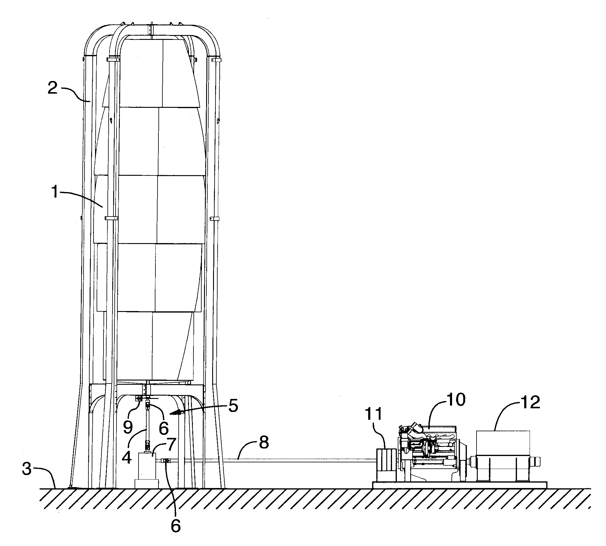
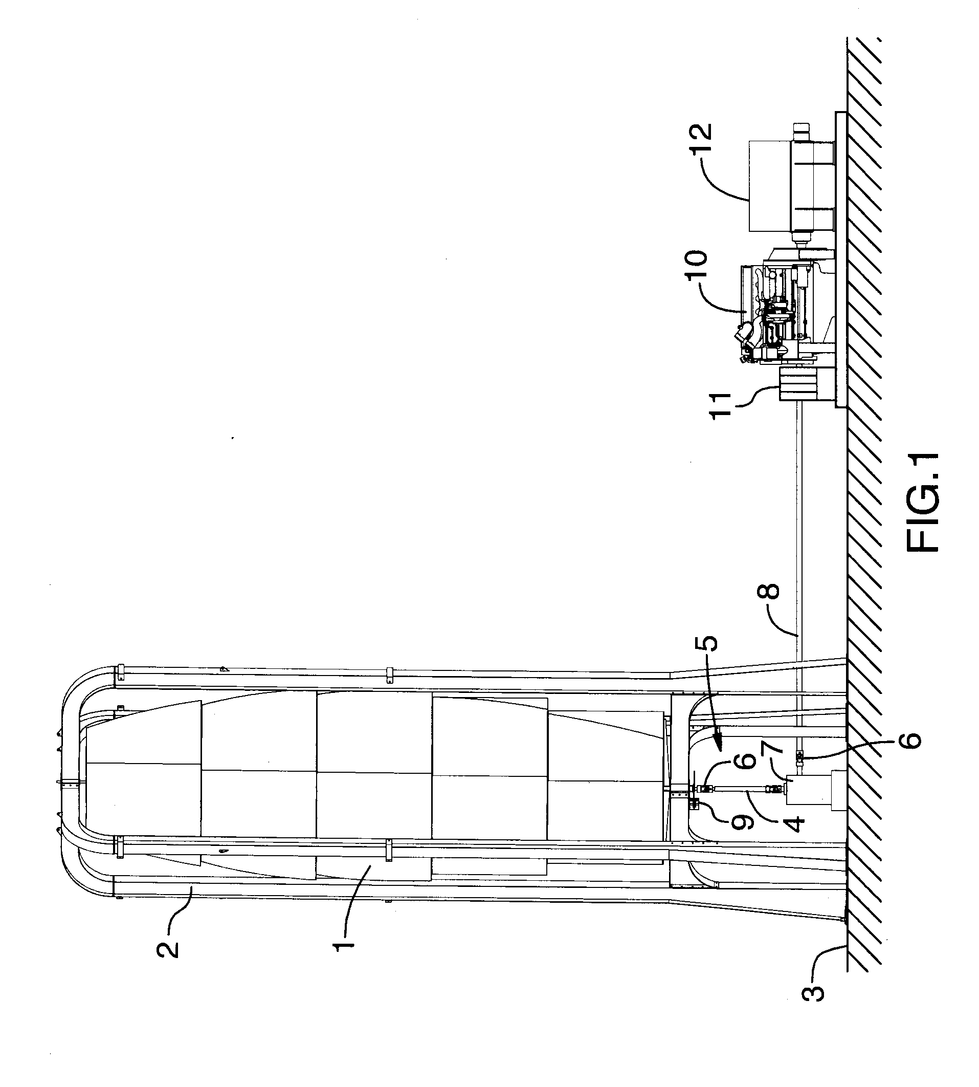
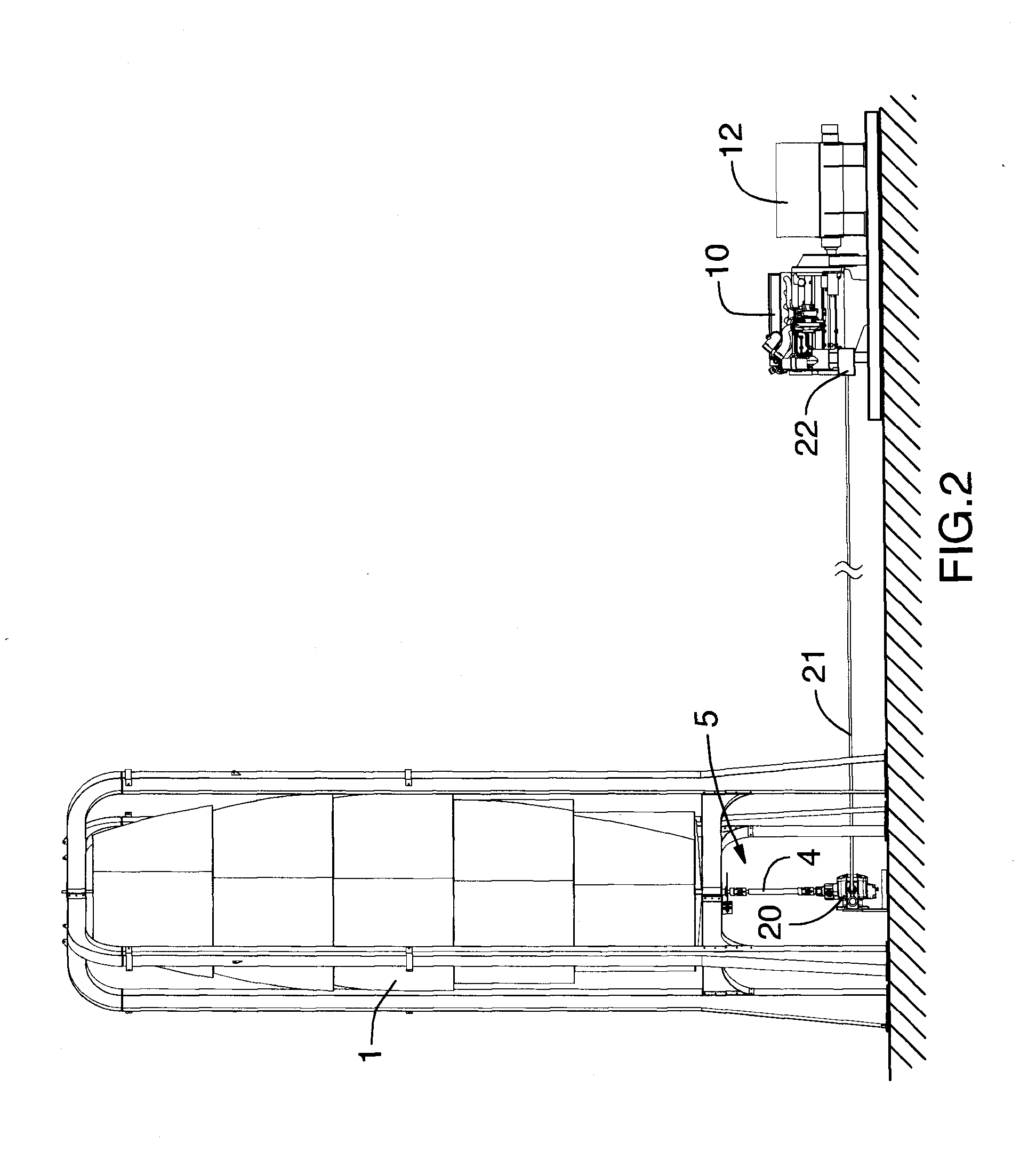
[0038]Referring to FIG. 1, a wind turbine 1 comprising a VAWT of the Savonius type is shown. The turbine 1 is secured within a mounting structure 2 that elevates the turbine relative to ground level 3. The turbine 1 has a vertical shaft 4 extending downwardly along the vertical centerline of the turbine to protrude beneath the turbine into the space 5 created within the boundary of the mounting structure 2 between the turbine 1 and ground level 3. Preferred embodiments of a turbine 1 suitable for use with the present invention are disclosed in co-pending U.S. patent application 61 / 053,018, which was filed on May 14, 2008, now U.S. Pat. No. 12 / 465,644, and in co-pending U.S. patent application 61 / 241,399, filed Sep. 11, 2009, all of which are incorporated herein by ...


PUM


Abstract

Provided is a wind powered system for reducing energy consumption of a power source, such as an internal combustion engine or an electric motor. In one embodiment, the wind powered system comprises a wind turbine operatively connected to an internal combustion engine, for example via a direct mechanical connection, a hydrostatic drive system or a pneumatic drive system in order to reduce the amount of fuel required by the engine to operate an electricity generating means. A controller may be optionally provided to modulate the load on the wind turbine in order to maximize the extraction of available power according to local wind conditions. In another embodiment, the wind turbine is connected to an air compressor for providing a supply of air in order to offset energy consumption of a conventional compressed air system.

Description

FIELD OF THE INVENTION[0001]The invention relates to wind powered systems for generating supplemental power to offset the energy consumption of a primary power source. In certain embodiments, the invention relates to the interconnection between a wind powered apparatus and an electricity generator powered by a fuel consuming primary power source, such as an internal combustion engine, wherein the wind powered apparatus is used to offset some of the load on the primary power source, thereby decreasing the fuel consumption thereof to produce a given amount of electricity. In other embodiments, the invention relates to the interconnection between a wind powered apparatus and an air compressor or blower in order to reduce the energy consumption thereof.BACKGROUND OF THE INVENTION[0002]Electric generators powered by internal combustion engines are used in a variety of mobile and stationary applications. For example, in remote communities diesel engine powered electric generators are used...

Claims


Application Information

Patent Timeline
Patent Type & Authority Applications(United States)
IPC IPC(8): F03D9/00H02P9/04F02B65/00
CPCF02B73/00Y02E10/725F05B2220/70F03D9/00Y02E10/72Y02E60/16Y02E70/30F03D9/17F03D9/20F03D9/28F03D13/20F03D15/10
Inventor HALL, RONALDBALL, JOHN BRADLEYBRUNET, ROBERT ALLEN HENRY
Owner HALL RONALD
Why Eureka
Try Eureka