Self-stemming cartridge

a self-stemming and cartridge technology, applied in the direction of blasting cartridges, weapons, weapons, etc., can solve the problems of large risk to mine workers, difficult to work at the site for extended periods of time, and fragments of rock to be projected from the explosion site, etc., to achieve the effect of easy combustible material

Inactive Publication Date: 2017-11-21
FOWLDS 3
View PDF22 Cites 0 Cited by
  • Summary
  • Abstract
  • Description
  • Claims
  • Application Information

AI Technical Summary

Benefits of technology

[0016]In accordance with a first aspect of the invention there is provided a cartridge which includes an elongate tube having a central body closed at each end and containing a gas producing substance, the cartridge being characterised in that the tube is made of a plastics material capable of outward deformation, with a band of an elastically deformable material provided about the tube adjacent an end that is to be stemmed and configured so that, in use, internal pressure in the tube caused by initiation of the gas producing substance results in outward deformation of the body and the band being effectively urged into sealing contact with a surrounding wall of a borehole to stem the borehole prior to any subsequent rupture of the elongate tube or dislodgment of any closure from the tube.
[0020]Still further features of the invention provide for the or each closure to be fastened to the tube by means of a screw thread arrangement; and for the tube to include a detent so as to prevent removal of the or each closure from the tube once secured thereto.
[0022]Yet further features provide for a fuse head to be external to the cartridge; for the fuse head to be held within a spigot which is attachable to the cartridge by means of a screw thread arrangement; for an operating cable to extend externally from the spigot; and for the spigot to include a detent so as to prevent removal thereof from the cartridge once secured.

Problems solved by technology

The problem with detonating explosives is that the ignition of the explosive is followed by a violent shockwave which may cause rock fragments to be projected from the explosion site.
The projected rock fragments pose a great risk to mine workers, thus commonly requiring a large area surrounding the blasting site to be cleared.
Furthermore, the pulverisation of the rock may create a dense cloud of dust surrounding the blasting site, making it impossible to work at the site for extended periods of time.
The problems associated with traditional methods of blasting or breaking rock resulted in the development of rock breaking explosives commonly referred to as non-detonating explosives.
The packed particulate material keeps the gases created by the cartridge within the borehole once the cartridge has been ignited resulting in high pressure being created within the borehole.
A drawback of non-detonating explosives is that adequate stemming of the borehole is of utmost importance, failure of which may cause some of the gas to escape thereby reducing the pressure exerted on the rock and causing the cartridge to be less effective.
Furthermore, stemming of boreholes that run at a downward slope may be difficult thus often being very time consuming to achieve.
Drawbacks of the disclosed cartridge include the cartridge having a plug at one end which will be ejected from the cartridge prior to stemming, thus causing the stemming operation to stop and the cartridge to be ejected from the borehole without breaking any of the rock.
It is thus highly unlikely that the cone will operate to expand the sheath.
Also, such flexing will cause the development of empty pockets within the sheath into which the gas can move, thus causing a drop in pressure within the cartridge and resulting in a cessation of combustion of the gas generating compound.
A further disadvantage of the cartridge disclosed in U.S. Pat. No. 8,342,095 is that the sheath is a solid tube and thus unlikely to expand sufficiently to stem the hole.
Also, the detonator cord runs between cone and sheath creating a gap which will permit gas to escape and thus prevent proper working of the cartridge during manufacture and handling.
This will create an inherently dangerous situation during assembly as there is a possibility of the detonator igniting the propellant during assembly.
There is no evidence of the cartridges proposed by U.S. Pat. No. 8,342,095 being commercially available and the applicant believes this to be a result of these not being capable of functioning for the reasons given above.

Method used


Image

  • Self-stemming cartridge
  • Self-stemming cartridge
  • Self-stemming cartridge

Examples


first embodiment

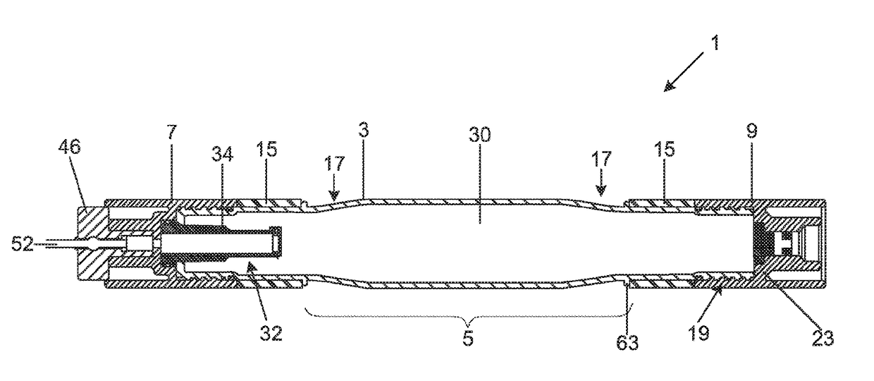
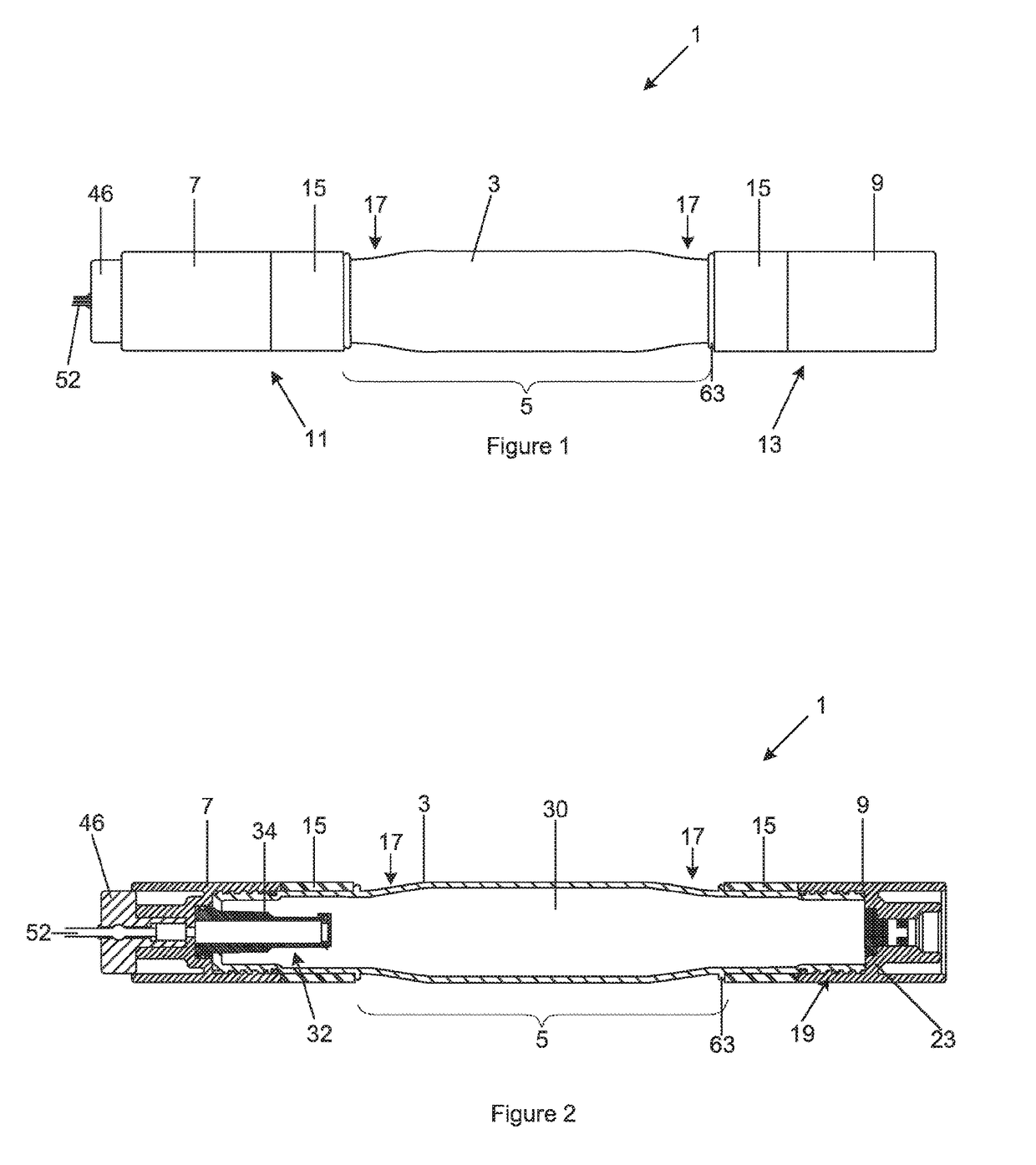
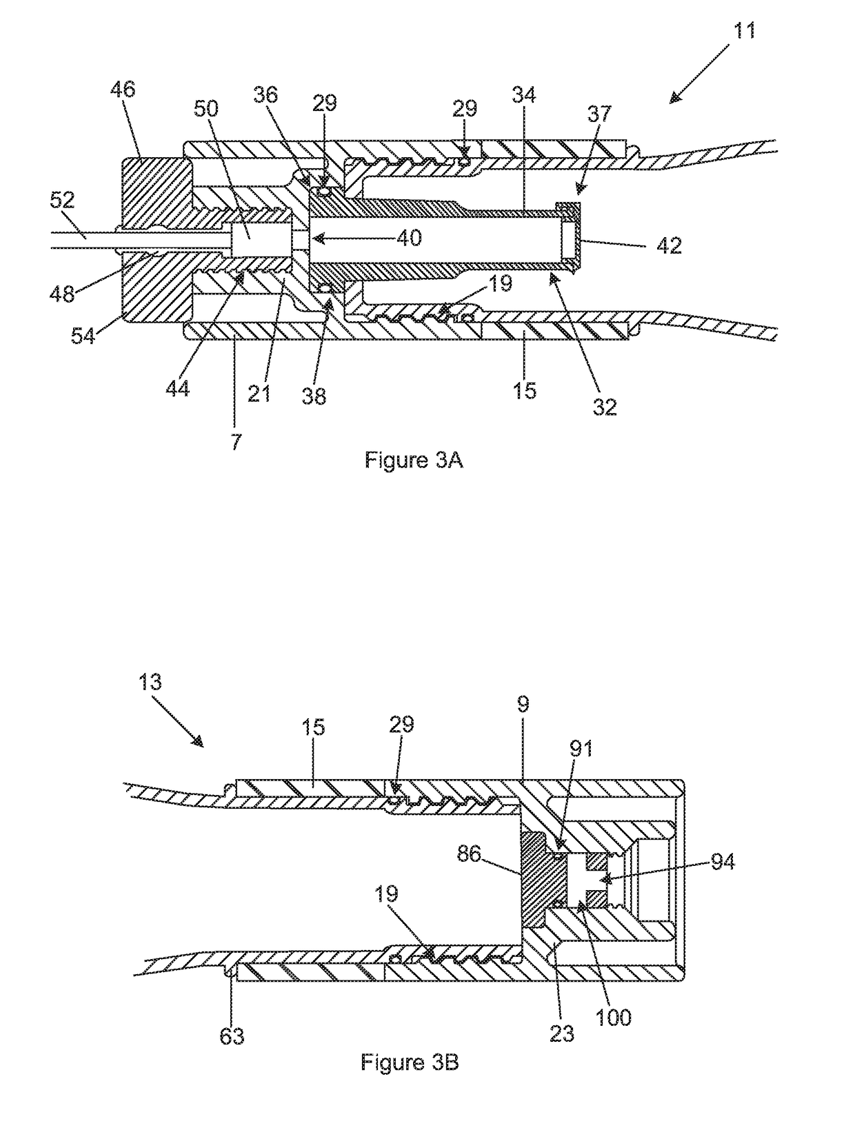
[0040]cartridge (1) and various components thereof is shown in FIGS. 1 to 10 and includes an elongate tube (3) having a central body (5) with closures (7, 9) at each end (11, 13) thereof. A band (15) of an elastic material is provided about the tube (3) adjacent each closure (7, 9). In this embodiment, the tube (3) has a radiused, inwardly tapered shoulder (17) spaced apart from each end (11, 13) such that the ends have a smaller diameter than the central body (5). This permits the cartridge (1) to have a substantially uniform diameter along its entire length.

[0041]The tube (3) is made, in this embodiment, from low density polyethylene (LDPE) which is selected to permit outward deformation of the tube (3). However, high density polyethylene (HDPE), ethylene vinyl acetate (EVA) or polyvinyl chloride (PVC) may also be used and can be moulded by injection or blow moulding. The body (5) has a wall thickness of between 1 mm and 3 mm while the ends (7, 9) have a thickness about double tha...


PUM


Abstract

A cartridge (1) is provided which includes an elongate tube (3) having a central body (5) that is closed at each end (11, 13) and containing a gas producing substance (30) therein. The tube (3) is made from a plastics material that is capable of outward deformation and a band (15) of an elastically deformable material is provided about the tube (3) adjacent each closed end. The tube (3) is configured such that internal pressure in the tube (3) caused by initiation of the gas producing substance (30) results in outward deformation of the body (5) and each band (15) and subsequent rupture of the body (5) prior to the closed ends being ruptured or opened.

Description

CROSS-REFERENCE(S) TO RELATED APPLICATIONS[0001]This application is the National Stage of International Application No. PCT / IB2014 / 065817, filed on Nov. 5, 2014, which claims priority from South African provisional patent application number 2013 / 08286, filed on Nov. 5, 2013. The contents of both applications are hereby incorporated by reference in their entirety.FIELD OF THE INVENTION[0002]This invention relates to rock breaking and more specifically to cartridges used for breaking rock.[0003]The term “rock” as used herein covers natural rock and also includes concrete and similar structures that are to be broken up.BACKGROUND TO THE INVENTION[0004]Traditional methods of blasting or breaking rock in quarries and mines make use of high energy explosives, often referred to as detonating explosives. High energy explosives crush and pulverise the rock which can then be removed for either retrieving a sought after mineral within the rock or for disposal of the rock or both.[0005]The prob...

Claims


Application Information

Patent Timeline
Patent Type & Authority Patents(United States)
IPC IPC(8): F42D1/00F42B3/087F42D3/04
CPCF42D3/04F42B3/087
Inventor NIEUWOUDT, GERHARD
Owner FOWLDS 3
Why Eureka
Try Eureka